This blog documents the restoration, and conversion, of a 1965 Humber (Singer) Vogue to a fully electric vehicle. The Vogue will be powered by an 11kW(modified), 3 phase industrial AC motor, controlled by an industry standard Variable Speed Drive (VSD) or Inverter. To be able to produce the 400 volts phase to phase the VSD will need about 600 VDC of batteries. A big thanks to the contributors on the AEVA forum: http://forums.aeva.asn.au/forums/

Thursday, January 27, 2011

Controller Configuration and Window Regulators

I had a day off for the Australia Day holiday yesterday.
I removed the controller tray so that I could finalise the wiring of the lower 3 battery packs in the front.
The Charger connecting cables (made here) were not long enough for these 3 lower packs so I extended them by about 120mm.

I also did a task that I have been putting off - cleaning and re-greasing the window regulators - (for the hand operated side windows).

Finally I spent about 3 hours or more putting my custom configuration into the controller. Since the controller was out of the car I took it inside and ran it from an 18 VDC plug pack. The power section isn't active but otherwise you can do everything you need to operating it in this way.
The PC software allows you to monitor digital and analogue signals that are present internally and see them graphically on a monitor window.


I had made a couple of minor mistakes but the major time user was getting used to idiosyncrasies of the Lenze PC software.

Thursday, January 20, 2011

Vector Mode fully Stable

Due to a series of straight out mistakes I actually didn't have the shaft encoder wired up correctly.
Last night I wired it up properly, enabled it and ran the motor flawlessly in Vector mode.
Now to put in my configuration for accelerator control. I guess I'd better build the mount for the accelerator pedal sometime soon.

Later edit (so I have these documented somewhere).
The motor values I entered into the controller for were:
22kW, 2960 RPM, 100 Hz, 41.3A, 440 V, 0.78 cos theta.
Param  Value
22     88.5 Motor MaxA
23     50 Gen MaxA
81     22 kW
87     2960 RPM
88     41.3 Nom. A
89     100 Hz
90     440 V
91     0.78


Which resulted in the controller's auto-tune setting these values:
Param  Value
82     0.044
84     97.77
85     0.9
92     17.8

Wednesday, January 19, 2011

Motor Control Tuning and Stability

Getting the controller to run perfectly with the motor is becoming a challenge.
I have had it "Auto-ID" once correctly but I can not get it to tune to the motor again.
Why bother? According to the Lenze manual the drive should be re-tuned if you connect the motor temperature monitoring - which I have done. I still get a bit of motor shaking at about 400 RPM which I am trying to tune out (not motor balance - V/F mode is a smooth as silk).
A bit technical but the short of it is that I need this mode working properly if I am to implement the accelerator control I want.

Tuesday, January 18, 2011

Traction Cabling in Progress

This post preceeds the previous post in time - pictures taken over the past two weeks.
Here are some photos that my son took while installing the main cable and battery trays shown in the previous post. This one is me heat-shrinking a crimp. I wonder how these crimps done in Melbourne's recent very humid week will last.

Another action shot.

Engine bay prior to installing the controller tray and top battery tray. I really will replace the garbage bag tie with cable ties when I tidy the wiring.

This is the contactor and current sensor box. These two contactors are for safety only. They join the return paths of the positive 300V and negative 300V halves together. This is not necessary for operation but makes the car a lot safer when the ignition is off. The small circuit board holds the AC752 hall-effect current sensor that will be used by the speedo cluster to measure and display battery current. The twisted pieces of copper that make the connection are more of the old copper fireplace screen used previously here.

The boot battery trays. Neoprene rubber lined like all the battery trays.


The tray for the four boot battery packs with cardboard battery pack. More neoprene....


William got this great shot from looking under the diff forward to the motor. I really have pressure cleaned the underside but I think it needs scrubbing as well - there is no loose dirt left.


The conduit going past the motor rear mounts. This way it won't get in the way if I have to remove the motor.


He got a better picture of the conduit going over the axle too.

Here is how the conduit gets into the boot. This is under the boot mounted contactor/fuse box on the left side of the car. It's all siliconed up now. You can just make out the conduit bracket on top of the axle that is mounted to the axle limiting rubber buffer. There has been no need to drill holes in any chassis rails.

Finally, a picture of the traction cable wiring prior to putting the top battery tray and controller tray in. The orange conduit running low down alongside the motor is the front-to-rear conduit shown a few pictures above. More garbage ties....

Monday, January 17, 2011

Conduit and Batteries Mounted

Three weeks of holidays over the Christmas and New Year break have ended for me but there has been considerable progress on the Vogue.
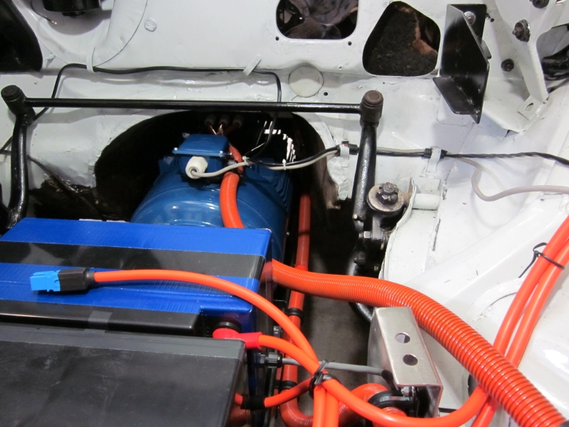
I had not intended to mount the rear battery packs permanently as I was waiting for my welder friend to be available but I finally decided to use the tray I had and reinforce it with 3mm Aluminium angle. It worked out fine. The set of four battery packs are held in with 6 x 1/4 Inch high tensile bolts (straps not fitted yet.). Like all the battery trays I am doing, the whole lot are surrounded by either 5mm or 2mm neoprene rubber to stop them sliding and cushion them from some vibration.

The fifth pack in the boot. Another custom battery tray. It has the strap fitted - a camlock buckle and webbing strap rated to 300kg.


As I pulled each pack out of storage I measured the terminal voltage. Most were between 52.6 and 52.9 Volts but there was one that was only 49.6V - alarm bells. I disassembled the pack to find 2 dead cells.
(Imagine picture of 2 cells with "Dead" written on them here!) No need - here it is.

I had bought 5 spares. It took about 25 minutes to change the bad ones out and the pack was good again.


The main conduit is also installed from the rear to the front of the car. It holds the feed and return cables for the 5 packs in the boot and the 240 VAC mains charger cables for the front 7 chargers.


I placed and drilled all the holes in the stainless steel controller tray - that was fun - not!
I haven't actually mounted the chargers or the DC-DC converter (pretend alternator) as the tray has to come out again before being installed permanently.

The little box on top of the left battery pack is my 12 VDC power supply (substitute 12 VDC battery which I haven't mounted yet - or purchased). I temporarily wired the four contactors up to close when the switch on the power supply is turned on.

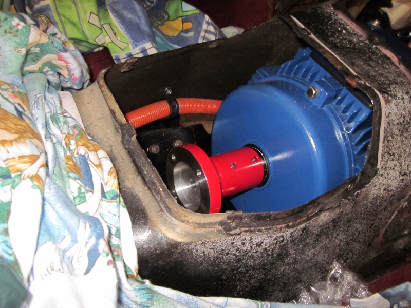
First power up was nicely uneventful and the motor ran well in V/F mode (a fairly "plain vanilla" mode for AC controllers). The trouble started when I performed an "Auto-ID" on the motor. Auto-ID is where a controller that isn't actually matched to a motor has to explore the motor's electrical characteristics to tune the pair together. I can not run the controller in Vector (preferred) mode to use Torque control to emulate an accelerator pedal unless Auto-ID works - it didn't.

I tried several combinations of motor data to no avail. I had a depressing night running possible alternative configurations through my mind but none would be a good as true Vector mode with Torque control.


At the end of a lot of experimenting, pack number 2 was down to 50.6 Volts when the other 11 packs were still at 52.6 Volts so I decided to charge pack #2 and balance it. It took  24 hours to balance. By this time it was Saturday morning with one day of my vacation left. I tried Auto-ID again and this time noted the fail code - ID1 which could mean "Motor too small". I changed the motor data to be a 22kW at 100Hz and IT WORKED. I quickly saved the parameter set - and wrote down the 4 results of the Auto-ID.


Sunday saw me try to catch up on 3 weeks of house chores that covered a very humid week where everything grew out of control.

Saturday, January 1, 2011

Boot (Trunk) Electrics

Even though it's been a month since I last posted, stuff HAS been happening - just slowly.
The rear of the car will hold 5 of the battery packs, the mains inlet/charger sequencer (controlling the 12 chargers not coming on all at once), and the rear high-current contactor and fuses.

This is the are of the boot where the fuel tank lived. It was mounted vertically in the Vogue with the filler on top of the guard. There are two mounting points, one on the guard and one coming off the rear of the car. They uses a metal strap to hold the tank.

Here is what I need to mount.
The left hand one has a circuit breaker and earth fault relay and my logic/relay board. The right hand one is almost the same as the fuse/contactor box in the engine bay.

Since my welder person is unavailable I will build the mounting bracket from aluminium angle and lots of 6mm bolts and nuts. Step 1 - two vertical pieces of angle and some support.

Step 2 - horizontal pieces space vertically to fit the mounting holes on both boxes.


Poking the camera into the gap in the guard you can see another piece of angle to support the front mount laterally.

 The boxes mounted. I have put the dummy battery below them to check for fit. I will have to remove the cover on the mains inlet/charger controller box the get the battery pack out but that's OK.

View from the rear of the car showing the bigger picture. I have since pulled the whole lot out to weigh it and paint that area of the boot as it looked pretty gungy with old fish oil stains.

Now I know where the rear contactor box is located (I didn't really know until I did it) I can install the front to rear conduit and start the high current wiring.