This is a kind of repeat of this post showing the motor going in but the motor is back in the car - for good (fingers crossed).
The terminal box is fitted and all the high current wiring is attached.
The black wire trailing out the side of the main terminal box is for the embedded motor temperature monitoring. The grey wire emerging from the small terminal box is for the shaft encoder. The unused black cable gland is for the motor fan wires.
View from the front of the car. I regret not putting the fan wires on - I'll need a cut-down screwdriver. I didn't want to attach it because the wire already has the correct connector on it, but I now realise I'll have to connect it before the battery cradles go in.
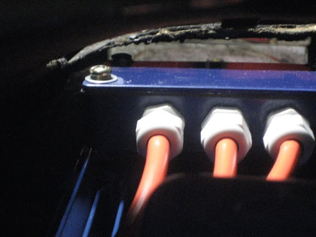
View from the engine bay, taken by poking the camera into the transmission tunnel. Not much clearance. The problem is the far left terminal cover bolt. I ground it down to about 1.5 to 2mm thick and used a star instead of spring washer. At least you can see daylight over it.
As with the previous photo, I couldn't actually see this - only the camera could. This is a view from inside the car poking the camera down into the area where my head doesn't fit. The one at the right is the tight one.
I also got the battery mounts de-rusted and primed and started on splash proofing the DC-DC converters.
More later...
This blog documents the restoration, and conversion, of a 1965 Humber (Singer) Vogue to a fully electric vehicle. The Vogue will be powered by an 11kW(modified), 3 phase industrial AC motor, controlled by an industry standard Variable Speed Drive (VSD) or Inverter. To be able to produce the 400 volts phase to phase the VSD will need about 600 VDC of batteries. A big thanks to the contributors on the AEVA forum: http://forums.aeva.asn.au/forums/
Monday, September 6, 2010
Subscribe to:
Post Comments (Atom)


No comments:
Post a Comment