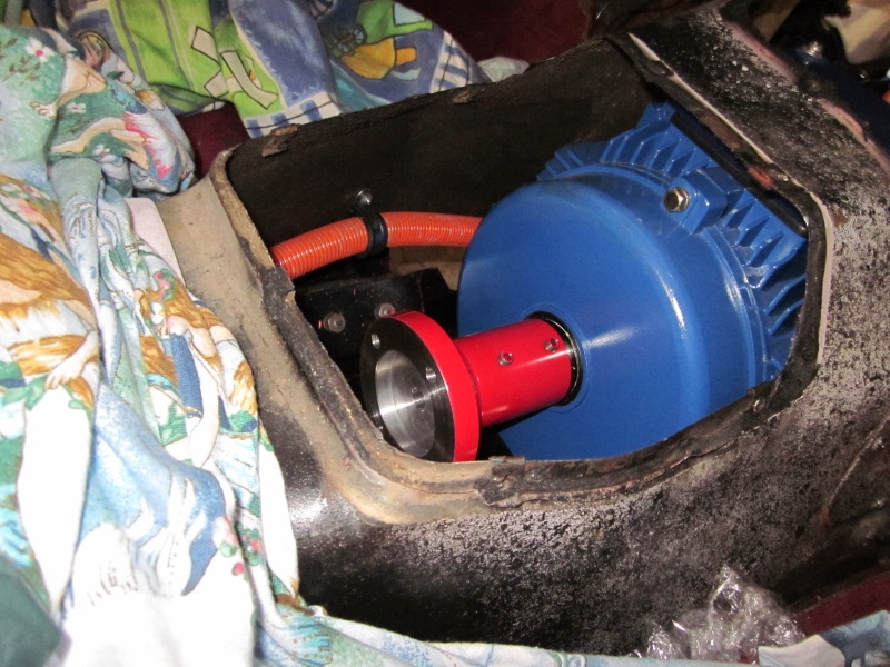
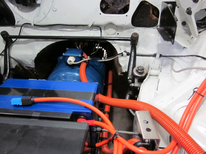
This blog documents the restoration, and conversion, of a 1965 Humber (Singer) Vogue to a fully electric vehicle. The Vogue will be powered by an 11kW(modified), 3 phase industrial AC motor, controlled by an industry standard Variable Speed Drive (VSD) or Inverter. To be able to produce the 400 volts phase to phase the VSD will need about 600 VDC of batteries. A big thanks to the contributors on the AEVA forum: http://forums.aeva.asn.au/forums/

Showing posts with label cable. Show all posts

Wednesday, January 25, 2012

Traction Battery Pack Schematic

Something I haven't included in the blog to date is the Traction Battery circuit.
The little blue connectors that connect some sub-packs to others are Anderson PP75 connectors. They are heatshrunk so as to provide finger-proof disconnects. When the "Traction Enable" is off, the entire pack is isolated from the Controller, Heater and DC-DC converters.
The term "VFD" refers to the motor controller - known sometimes as a Variable Frequency Drive.

(Later addition. I see that this page gets a lot of views so I should explain that the Vogue battery pack is a 600 VDC system - which is an unusually high voltage for an EV. I have divided this into two 300 VDC "half packs" - a positive and a negative set of packs. Each numbered pack is comprised of 32 x 10AH Headway LiFePO4 cells arranged as 16S2P - essentially 16 x 20AH cells.)
(Updated 08 Jan 2014)

Friday, August 12, 2011

Battery Pack and Traction Cable Placement

A bit of retrospective documentation here.
I have had this diagram since I decided on Lithium batteries but since the blog is my documentation I thought I'd better post it. The battery pack numbers are important as I have documented history on each pack as they have been modified and charged. Click on the image for a better view.
(Diagram updated 12th Sept 2011)

Friday, July 22, 2011

Reversing solved and Battery warning identified

Shortly after the previous post and before removing the controller tray, I got reverse working. I had removed a 'function block' from the FB list in the controller knowing that my configuration didn't use it and the Lenze manual said they didn't - well they do! It was a block called ANEG which takes an analogue signal and makes it negative. The particular block was used to feed the low torque limit in the motor control block.
Anyway - now the motor runs either way - good.

The problem of the low-battery alert going off was not caused by the battery pack. The pack/BMS tested out fine using a couple of fan heaters as a load. I was able to duplicate the error by lifting a connection from one cell-pair to another momentarily and it got me to thinking. The motor cables go very close to the pack that was spitting the error.


Right at the point where the motor cables go next to the pack - on the inside of the pack - are the BMS wires - lots of them and running almost parallel to the motor cables.


So it's reasonable to assume that there is either capacitive or inductive coupling  at play here.
To help with capacitive coupling I did the following:


Take an offcut of brass fly wire and attach some heavy wires.


Cover the mesh with waterproof gaffer tape. What a mess - but I'll hide it under the trays so no-one will ever know. Well almost no-one....


And re-install the pack in the car, adding bullet connectors to the wires connected to the fly wire sheild and grounding them. Actually the pack from this location is now in the boot and this is a different pack (pack #5) - just to see if pack #10 really did have a fault that I missed.
To help avoid inductive coupling, the motor cable conduit is now tied well away from the pack.

A vew from another angle to show height separation, grounding wires - and the messy tape.
Now to stick the trays back in and try it...

Tuesday, July 12, 2011

Engine Bay BMS and Charger cables connected

A task I have not been looking forward to is trying to get the tangle of cables for chargers and BMS monitoring layed out so they look halfway reasonable. The result is about what I expected - I hoped for better but....
The grey cables are for the BMS monitoring bus. The small red and black wires connect the chargers to each pack via a fuse and a pair of diodes. (The charger has a fuse in the positive lead - I added one in the negative lead).
 

This is typical of the wiring mess that I'll have to clean up. The big black box is the 150 Amp relay that isolates the DC-DC convertors from the battery - overkill, but as I said in an earlier post - I had it.

The lower of the two grey relays is the motor fan relay and the upper of these two is the start/run latch relay.

Tuesday, January 18, 2011

Traction Cabling in Progress

This post preceeds the previous post in time - pictures taken over the past two weeks.
Here are some photos that my son took while installing the main cable and battery trays shown in the previous post. This one is me heat-shrinking a crimp. I wonder how these crimps done in Melbourne's recent very humid week will last.

Another action shot.

Engine bay prior to installing the controller tray and top battery tray. I really will replace the garbage bag tie with cable ties when I tidy the wiring.

This is the contactor and current sensor box. These two contactors are for safety only. They join the return paths of the positive 300V and negative 300V halves together. This is not necessary for operation but makes the car a lot safer when the ignition is off. The small circuit board holds the AC752 hall-effect current sensor that will be used by the speedo cluster to measure and display battery current. The twisted pieces of copper that make the connection are more of the old copper fireplace screen used previously here.

The boot battery trays. Neoprene rubber lined like all the battery trays.


The tray for the four boot battery packs with cardboard battery pack. More neoprene....


William got this great shot from looking under the diff forward to the motor. I really have pressure cleaned the underside but I think it needs scrubbing as well - there is no loose dirt left.


The conduit going past the motor rear mounts. This way it won't get in the way if I have to remove the motor.


He got a better picture of the conduit going over the axle too.

Here is how the conduit gets into the boot. This is under the boot mounted contactor/fuse box on the left side of the car. It's all siliconed up now. You can just make out the conduit bracket on top of the axle that is mounted to the axle limiting rubber buffer. There has been no need to drill holes in any chassis rails.

Finally, a picture of the traction cable wiring prior to putting the top battery tray and controller tray in. The orange conduit running low down alongside the motor is the front-to-rear conduit shown a few pictures above. More garbage ties....

Monday, January 17, 2011

Conduit and Batteries Mounted

Three weeks of holidays over the Christmas and New Year break have ended for me but there has been considerable progress on the Vogue.
I had not intended to mount the rear battery packs permanently as I was waiting for my welder friend to be available but I finally decided to use the tray I had and reinforce it with 3mm Aluminium angle. It worked out fine. The set of four battery packs are held in with 6 x 1/4 Inch high tensile bolts (straps not fitted yet.). Like all the battery trays I am doing, the whole lot are surrounded by either 5mm or 2mm neoprene rubber to stop them sliding and cushion them from some vibration.

The fifth pack in the boot. Another custom battery tray. It has the strap fitted - a camlock buckle and webbing strap rated to 300kg.


As I pulled each pack out of storage I measured the terminal voltage. Most were between 52.6 and 52.9 Volts but there was one that was only 49.6V - alarm bells. I disassembled the pack to find 2 dead cells.
(Imagine picture of 2 cells with "Dead" written on them here!) No need - here it is.

I had bought 5 spares. It took about 25 minutes to change the bad ones out and the pack was good again.


The main conduit is also installed from the rear to the front of the car. It holds the feed and return cables for the 5 packs in the boot and the 240 VAC mains charger cables for the front 7 chargers.


I placed and drilled all the holes in the stainless steel controller tray - that was fun - not!
I haven't actually mounted the chargers or the DC-DC converter (pretend alternator) as the tray has to come out again before being installed permanently.

The little box on top of the left battery pack is my 12 VDC power supply (substitute 12 VDC battery which I haven't mounted yet - or purchased). I temporarily wired the four contactors up to close when the switch on the power supply is turned on.

First power up was nicely uneventful and the motor ran well in V/F mode (a fairly "plain vanilla" mode for AC controllers). The trouble started when I performed an "Auto-ID" on the motor. Auto-ID is where a controller that isn't actually matched to a motor has to explore the motor's electrical characteristics to tune the pair together. I can not run the controller in Vector (preferred) mode to use Torque control to emulate an accelerator pedal unless Auto-ID works - it didn't.

I tried several combinations of motor data to no avail. I had a depressing night running possible alternative configurations through my mind but none would be a good as true Vector mode with Torque control.


At the end of a lot of experimenting, pack number 2 was down to 50.6 Volts when the other 11 packs were still at 52.6 Volts so I decided to charge pack #2 and balance it. It took  24 hours to balance. By this time it was Saturday morning with one day of my vacation left. I tried Auto-ID again and this time noted the fail code - ID1 which could mean "Motor too small". I changed the motor data to be a 22kW at 100Hz and IT WORKED. I quickly saved the parameter set - and wrote down the 4 results of the Auto-ID.


Sunday saw me try to catch up on 3 weeks of house chores that covered a very humid week where everything grew out of control.

Friday, September 3, 2010

Battery and Motor cable has Arrived

The decision of which cable to get, and purchasing of battery "traction" cable has been a lot easier than I had thought. Assuming about 100 Amps maximum for battery current (I might peak 115 later with the upgraded controller), I have decided on 10mm2 cable. This cable is rated at about 1.9milliOhm per meter (at 20 degrees C) so for the 10 meter run to and from the boot should result in only a 2 Volts drop at 100 Amps. With a 600 Volts system, that's not much.

I have purchased a double insulated very flexible 10mm2 welding cable from Arrid. Tycab ZDU132202. This was just under AU$2 per meter with $17 shipping. (It's a good range going up to 120mm2). I estimated I'd need 30 meters (using Sketchup) but since it was fairly inexpensive I bought 45 meters in case I decided to do a double run to the boot (trunk) packs.

I had already got cable lugs from the ToolBoxShop in the UK and a Crimping tool from eBay - hex crimp, double action with switchable dies. (The tea towel is so I don't scratch the glass-top table I use for taking photos.)
 
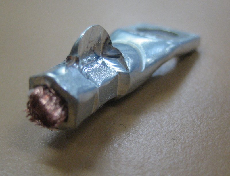
Amongst others, the crimper has a 10mm2 setting and a 16mm2 setting. First I tried the 10mm2 setting - too tight! The metal has to go somewhere - it went up!
I also tried the 16mm2 setting - too loose. (The crimp closer to the wire is the 16mm2.)

 
Well Goldilocks - what to do now. I set one side to 16mm2 and the other side to 10mm2. The result was a good crimp.

I couldn't help it - I had to heat shrink it! The total diameter of the cable is 9.3mm and the copper core is only 4.5mm so it looks like they are over-crimped but I'm pretty sure they are OK.

These are the three motor cables ready to connect to the motor terminal box this weekend and get the motor back into the car. Most likely I won't be able to get at the connections once the motor is back in position.