I have uploaded a better quality version of the Video to Youtube.
Friday, July 29, 2011
Better Quality Video of First Drive
SORRY - I'LL FIX THIS WHEN I FIND THE VIDEO AGAIN.
I have uploaded a better quality version of the Video to Youtube.
I have uploaded a better quality version of the Video to Youtube.
Sunday, July 24, 2011
First Drive - It's Not a Mixmaster!
The first time Laurel, my other half, saw and heard the motor running in the Vogue she indicated that she hoped I wasn't building a Mixmaster - a device that made whirring noises but didn't move. The Mixmaster joke has been ongoing in our family for almost a year now.
I put the Driveshaft in last night. We waited all morning for the rain showers to stop then just after lunch checked the weather radar map again and it showed clear for a couple of hours. The covers came off for the first time in about a year. I'm holding the keys.
 The bonnet closed. Curously I was glad to see it still did!
Some quick video editing and...


I put the Driveshaft in last night. We waited all morning for the rain showers to stop then just after lunch checked the weather radar map again and it showed clear for a couple of hours. The covers came off for the first time in about a year. I'm holding the keys.

Some quick video editing and...
Laurel says it's officially NOT a Mixmaster.
I should have put the dashboard in but I was really wanting to see it move. The fiddling with clip leads is to select forward/reverse. The ignition system and safeties were all operating.
Some stills.
About the only electric thing left to do is mount those rear chargers that you can see lying around in the boot.

There was an interesting moment halfway up the street where I stopped and some neighbours were in their driveway putting stuff in the boot of their car. The Vogue brakes gave a little squeak when it stopped and they looked up in time to see it silently take off in reverse - a priceless look. It's the next driveway up on the left from where the Vogue is in this shot.

Now for some lights, trim, glass, rubber, pinchweld, etc....
Some Fiddly bits
I hadn't expected to remove the controller tray quite so soon so had short-cut on a couple of items. The outputs of the DC-DC convertors were wired directly up to the 150A relay and since it had now become a "wiring loom" I needed to add some easy-to-unplug connectors. I also hadn't put a connector in the wire to the +300V contactor coil. I cut them both at a carefully considered point when removing the controller tray.

Here's a trick when soldering small connector pins. A handy vice made out of needle nose pliers and a rubber band. (Speaker connectors from SRM9000 radio.)

I use the same trick when holding connectors to be soldered. For the 20 Amp DC-DC wires I used a couple of XT60 connectors. These are another connector favoured by the serious RC Aeroplane guys/gals. I wish I had known about these before using the Deans connectors on the chargers.

Car side of connectors finished.
Ya gotta love heatshrink!
Once everything was refitted, the motor went fine with no battery warning alert when run. Strangely, the blue LED on battery pack #2 is faulty again. I'll get to that one night next week - maybe it's just coincidence. Now to fit the tailshaft.
Friday, July 22, 2011
Reversing solved and Battery warning identified
Shortly after the previous post and before removing the controller tray, I got reverse working. I had removed a 'function block' from the FB list in the controller knowing that my configuration didn't use it and the Lenze manual said they didn't - well they do! It was a block called ANEG which takes an analogue signal and makes it negative. The particular block was used to feed the low torque limit in the motor control block.
Anyway - now the motor runs either way - good.
The problem of the low-battery alert going off was not caused by the battery pack. The pack/BMS tested out fine using a couple of fan heaters as a load. I was able to duplicate the error by lifting a connection from one cell-pair to another momentarily and it got me to thinking. The motor cables go very close to the pack that was spitting the error.


Right at the point where the motor cables go next to the pack - on the inside of the pack - are the BMS wires - lots of them and running almost parallel to the motor cables.
So it's reasonable to assume that there is either capacitive or inductive coupling at play here.
To help with capacitive coupling I did the following:

Take an offcut of brass fly wire and attach some heavy wires.

Cover the mesh with waterproof gaffer tape. What a mess - but I'll hide it under the trays so no-one will ever know. Well almost no-one....
And re-install the pack in the car, adding bullet connectors to the wires connected to the fly wire sheild and grounding them. Actually the pack from this location is now in the boot and this is a different pack (pack #5) - just to see if pack #10 really did have a fault that I missed.
To help avoid inductive coupling, the motor cable conduit is now tied well away from the pack.

A vew from another angle to show height separation, grounding wires - and the messy tape.
 Now to stick the trays back in and try it...
Anyway - now the motor runs either way - good.
The problem of the low-battery alert going off was not caused by the battery pack. The pack/BMS tested out fine using a couple of fan heaters as a load. I was able to duplicate the error by lifting a connection from one cell-pair to another momentarily and it got me to thinking. The motor cables go very close to the pack that was spitting the error.


Right at the point where the motor cables go next to the pack - on the inside of the pack - are the BMS wires - lots of them and running almost parallel to the motor cables.
So it's reasonable to assume that there is either capacitive or inductive coupling at play here.
To help with capacitive coupling I did the following:

Take an offcut of brass fly wire and attach some heavy wires.

Cover the mesh with waterproof gaffer tape. What a mess - but I'll hide it under the trays so no-one will ever know. Well almost no-one....
And re-install the pack in the car, adding bullet connectors to the wires connected to the fly wire sheild and grounding them. Actually the pack from this location is now in the boot and this is a different pack (pack #5) - just to see if pack #10 really did have a fault that I missed.
To help avoid inductive coupling, the motor cable conduit is now tied well away from the pack.

A vew from another angle to show height separation, grounding wires - and the messy tape.

Wednesday, July 20, 2011
Commissioning Woes
Well the Engine Bay wiring was pretty much completed by Monday at about 4PM. Everyone stood back at a safe distance and we turned the key to 'Start' - nothing happened. A quick think and I realised that the Charger inhibit wire to the boot (so the car will not go if the charger is connected) was not connected to anything. I clipped it to vehicle ground and turning the key to 'Start' resulted in a satisfying clunk as all the contactors closed. The 12 V battery now read 13.7 volts - good.
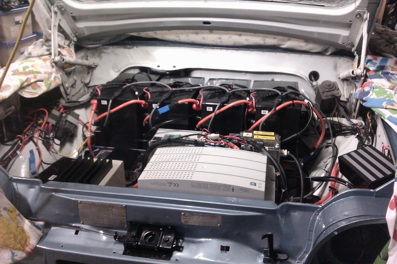
The completed engine bay.

Now the problems.
The controller has 4 digital outputs and 6 digital inputs. I need 4 of each. One digital output is used as a 24 VDC source for the 24 V logic on the digital inputs to the controller. This output appears to be 'fried'. No matter what I do it stays at 0 V. It turns out that digital input 4 is the culprit. For some reason it draws enourmous amounts of current and destroyed the output I was using for 24 Volts. I had assumed (when you assume you make an Ass out of U and Me) that the outputs would be current limited - not so - they just blow up. Anyway, I stopped using that particular input and swapped to another output for 24V and got a bit closer to everything working.
Once the above was sorted out we broke for dinner and afterwards I downloaded the prepared configuration into the controller. This is the first time I have run the controller in Torque mode and - IT WORKED!
Next problem - it would not make the motor go in reverse. I left that until I had time to think about it and review the configuration.
One final issue is that when I selected forward or reverse, both of which enable the motor outputs of the controller, I get a warning from the low 3 battery pack opto bus - the packs UNDER the controller tray. (Couldn't it have been any of the other seven battery packs?) Crawling under the car showed the the indicator light for pack #10 (the rearmost of the three packs under the trays), was going out when the alert sounded. Strangely, measuring the voltage of the pack when the problem happened showed 52.7 VDC - the same as the rest of the packs.
So 2 hours later with pack #10 removed for examination, I took this picture.

Pack #10 is now on my bench inside with the lid off. According to my modification notes (when I modified the packs), pack #10 was the only one that had clear signs of a short when it was being made. A flat washer had a quarter blown off and there was black residue on the top of the cell it was attached to (no, I didn't do it).
Now where do I get a 5 Ohm, 200 Watt resistor to use as a test load? Counting portable electric heaters now - each one is good for about 2 Amps at 50 Volts...
The completed engine bay.
Now the problems.
The controller has 4 digital outputs and 6 digital inputs. I need 4 of each. One digital output is used as a 24 VDC source for the 24 V logic on the digital inputs to the controller. This output appears to be 'fried'. No matter what I do it stays at 0 V. It turns out that digital input 4 is the culprit. For some reason it draws enourmous amounts of current and destroyed the output I was using for 24 Volts. I had assumed (when you assume you make an Ass out of U and Me) that the outputs would be current limited - not so - they just blow up. Anyway, I stopped using that particular input and swapped to another output for 24V and got a bit closer to everything working.
Once the above was sorted out we broke for dinner and afterwards I downloaded the prepared configuration into the controller. This is the first time I have run the controller in Torque mode and - IT WORKED!
Next problem - it would not make the motor go in reverse. I left that until I had time to think about it and review the configuration.
One final issue is that when I selected forward or reverse, both of which enable the motor outputs of the controller, I get a warning from the low 3 battery pack opto bus - the packs UNDER the controller tray. (Couldn't it have been any of the other seven battery packs?) Crawling under the car showed the the indicator light for pack #10 (the rearmost of the three packs under the trays), was going out when the alert sounded. Strangely, measuring the voltage of the pack when the problem happened showed 52.7 VDC - the same as the rest of the packs.
So 2 hours later with pack #10 removed for examination, I took this picture.

Pack #10 is now on my bench inside with the lid off. According to my modification notes (when I modified the packs), pack #10 was the only one that had clear signs of a short when it was being made. A flat washer had a quarter blown off and there was black residue on the top of the cell it was attached to (no, I didn't do it).
Now where do I get a 5 Ohm, 200 Watt resistor to use as a test load? Counting portable electric heaters now - each one is good for about 2 Amps at 50 Volts...
Saturday, July 16, 2011
Back into it - Rear packs permanently mounted.
We took a brief holiday up to Hepburn/Daylesford on Wednesday/Thursday (just the better half and me) - back Friday lunchtime so I didn't get much done since my previous post. On Friday afternoon I removed the rear packs, added the tie down straps and mounted the tray permanently. The tray is held in by 6 x 1/4" high tensile bolts with large flat washers under the bolt head and and underneath the car (not that the Vogue bodywork needs them on the underside).
I also added the charger connections and made the BMS monitoring cable then added the connectors to the cable running up to the engine bay. I used a DB-9 male/female pair. I had a little setback when upon testing the BMS monitoring. Pack numbers 2 and 5 didn't light up the Blue LED. Pack 2 had a cooked LED (to enthusiastic with heatshrink me thinks) and pack 5 had the +/- connections for the 12V enable back to front (didn't I test that?). I fixed both of them Friday night. I haven't mounted the rear chargers yet.
Here is a picture of the five rear packs plugged into their chargers temporarily.
The packs without the blue LEDs on are already charged and are balancing internally.

Tuesday, July 12, 2011
Engine Bay BMS and Charger cables connected
A task I have not been looking forward to is trying to get the tangle of cables for chargers and BMS monitoring layed out so they look halfway reasonable. The result is about what I expected - I hoped for better but....
The grey cables are for the BMS monitoring bus. The small red and black wires connect the chargers to each pack via a fuse and a pair of diodes. (The charger has a fuse in the positive lead - I added one in the negative lead).


This is typical of the wiring mess that I'll have to clean up. The big black box is the 150 Amp relay that isolates the DC-DC convertors from the battery - overkill, but as I said in an earlier post - I had it.
The lower of the two grey relays is the motor fan relay and the upper of these two is the start/run latch relay.
Friday, July 8, 2011
Chargers, Contactor/Fuse and DC-DC Mounted
It's been a pain getting everything mounted. Even though I made the hard-to-get-at bolts captive (epoxied from underneath), it still took an hour and a half to get these components mounted.
Then the thought struck me. I had always intended to make everything on the controller tray plug into the rest of the wiring so I could get it out easily - fully populated (except for the actual controller).
Why on earth didn't I mount everything first?
The reason is that the controller tray does not easily go in if the top battery tray is in - well it isn't.
Never mind - as long as I remmeber it next time I have to remove the trays. Remove the top battery tray FIRST!
Picture of chargers (right and centre), Contactor/Fuse box and DC-DC (left).
 Now add the motor Controller.


I am using Anderson PPL connectors for the + and - 300 VDC (and pack centre) connections to the DC-DC and heater. Shown are the blue/white/black connections for the DC-DC convertors. (The DC-DC convertors take the + and - 300 VDC and change it to 13.7 Volts DC at up to 40 Amps to run the Vogue 12 V electrics - headlights etc.). We carefully set both of them to 13.7 Volts with a 200mA load so that they draw the same from both halves of the full pack.
Then the thought struck me. I had always intended to make everything on the controller tray plug into the rest of the wiring so I could get it out easily - fully populated (except for the actual controller).
Why on earth didn't I mount everything first?
The reason is that the controller tray does not easily go in if the top battery tray is in - well it isn't.
Never mind - as long as I remmeber it next time I have to remove the trays. Remove the top battery tray FIRST!
Picture of chargers (right and centre), Contactor/Fuse box and DC-DC (left).


I am using Anderson PPL connectors for the + and - 300 VDC (and pack centre) connections to the DC-DC and heater. Shown are the blue/white/black connections for the DC-DC convertors. (The DC-DC convertors take the + and - 300 VDC and change it to 13.7 Volts DC at up to 40 Amps to run the Vogue 12 V electrics - headlights etc.). We carefully set both of them to 13.7 Volts with a 200mA load so that they draw the same from both halves of the full pack.
Thursday, July 7, 2011
Lower Batteries Re-Installed
I have started re-asembling the electical system in the car. The lower three battery packs have been secured and the charger cables attached. I used two 300kg camlock straps per battery pack for these three. It's going to be a real pain tightening them later on. Even so I decided not to have the buckles under the car. As mentioned earlier in the blog, these three have waterproof tape around the joins as they are more exposed than any of the other packs in the car. (Note that packs #10 and #12 have their numbers transposed here - this has been corrected.)
 The grey wires over the top of the packs are for the battery monitoring system.
After tidying up the wiring, the controller tray was installed.
 Shortly after taking this picture I realised I had trapped the motor temperature monitor wire under the tray (the black wire at the rear right). I loosened the rear bolts and freed it - fortunately it wasn't damaged.

After tidying up the wiring, the controller tray was installed.

Wednesday, June 29, 2011
Dashboard Software Finished (except for fiddling)
Like all home-project software, the dash/speedo will never be finished - but it now has everything I wanted it to have - and the displays are all glued in (silicone)!
Main display
- Instantaneous current
- Battery pack voltage
- Speed
- Estimated range remaining in 10 meters steps
Left 16x2 display
- State of Charge easy indication
- AH used (for more complicated evaluation of battery pack)
Right 16x2 display
- Trip meter in 10 meter steps
- Odometer in km (I might change this to 100 meter steps)
 Even when I used the flash the 16x2 displays are quite readable.
I also added some special characters so the SOC indication could have 80 steps rather than only 16. It's resolution is now 200mA/.Hr or 0.2 AH. Note that the last bar is thinner because we have 14.6AH remaining.
 All I have to do now is clean up the display wiring and mount the assembly into the speedo housing. The captive nuts are already installed and the holes have been drilled in the housing. I have to make a gasket for the front cowl (that holds the perspex front on) but that should be a small task.
 Next week I'm off work for some real EV progress!
Main display
- Instantaneous current
- Battery pack voltage
- Speed
- Estimated range remaining in 10 meters steps
Left 16x2 display
- State of Charge easy indication
- AH used (for more complicated evaluation of battery pack)
Right 16x2 display
- Trip meter in 10 meter steps
- Odometer in km (I might change this to 100 meter steps)

I also added some special characters so the SOC indication could have 80 steps rather than only 16. It's resolution is now 200mA/.Hr or 0.2 AH. Note that the last bar is thinner because we have 14.6AH remaining.


Friday, June 17, 2011
More Dashboard Software
This picture shows the battery bar indicator after I have used 14 Amp Hours from the pack.
The display on the left is the one in question. I'm still messing with the stuff on the main display - note it now says Amps and Volts.

The display on the left is the one in question. I'm still messing with the stuff on the main display - note it now says Amps and Volts.

Thursday, June 16, 2011
Dashboard Software
We have been having our driveway replaced over the last two weeks and the guys stored some of their gear in the garage in front of the Vogue so it was difficult to get access. I took the opportunity to get some work done on the software for the Speedo cluster. After an embarrasingly long time I finally got the 16x2 white on blue display working (The SPI bus for the big display shares some of the 8 bit data lines to the 16x2 displays - I didn't realise for a long time that I had to suspend SPI when writing to the parallel port D on the PIC).
This picture is of the almost-first thing I displayed. (The display on the left is the new one.)

This is the most likely contender for the battery State Of Charge indication (display on left). The number increases as I use power from the pack and should not be able to go above 20.00 (since it's a 20AH pack). The bar graph shows one block for each AH remaining in the pack. It starts at 16 and when it is empty it means I have used 80% of the pack capacity (4 AH remaining). I may place a message on the display when the bar graph is at zero. Something like " CHARGE NOW! ".

I can now wire the other 16x2 display and mount them both then finish and seal the speedo housing. I can update the software later with a USB port (and USB to serial) on my laptop.
Friday, May 27, 2011
Speedo internal wiring
I have finished a little sub-circuit board that links my main uProcessor board to the three displays.
The two lines of pins are for the two 16 x 2 line white-on-blue LCD displays. The connector hanging out the front is for my main display. The red heat-shrunk wires will have a four pin connector on them that connects to the trip reset button and up/down buttons (contrast/menu selections). The black wire with the RJ45 connector (bottom of picture) is so I can re-program the Flash without having to remove the speedo from the car or remove any covers. It will be accessible from underneath the dash once it is installed.
I'll tidy the wires up and secure them when the displays are in and the layout is locked down. I have yet to connect wires to the DB15 connector that will be secured to the rear of the speedo housing.

Closeup. Thanks to Theo for the fiddly soldering on the two fine-pitch connectors.

Next job is to wire the DB15 then the stressful task of gluing the main display to the front panel (silicone), without getting any bleeding out to the front.
The two lines of pins are for the two 16 x 2 line white-on-blue LCD displays. The connector hanging out the front is for my main display. The red heat-shrunk wires will have a four pin connector on them that connects to the trip reset button and up/down buttons (contrast/menu selections). The black wire with the RJ45 connector (bottom of picture) is so I can re-program the Flash without having to remove the speedo from the car or remove any covers. It will be accessible from underneath the dash once it is installed.
I'll tidy the wires up and secure them when the displays are in and the layout is locked down. I have yet to connect wires to the DB15 connector that will be secured to the rear of the speedo housing.
Closeup. Thanks to Theo for the fiddly soldering on the two fine-pitch connectors.
Next job is to wire the DB15 then the stressful task of gluing the main display to the front panel (silicone), without getting any bleeding out to the front.
Sunday, May 22, 2011
Speedo, ODO and other Gauges
As mentioned earlier in this blog, I have no speedo cable therefore I can not use the original mechanical speedo. One of the many side projects (that most EVers do NOT have to do), is to make a new speedo cluster. The brief is easy - it should show:
The "smarts" in the dash will provided by the guts of a proto-type of this Control Unit (for the SIMOCO mobile radio). This one is called a 9022, it runs a PIC 18F6627 microprocessor which gives me plenty of Digital inputs, outputs and Analogue inputs.

The other huge advantage of using this as a base is that display drivers have already been written and the development system is already set up and running. It's an area of software projects that I dislike - having to set up new environments and get used to them. While I didn't write the CU software in these products, I was familiar enough with them where my learning curve was quite fast.
The display itself was not big enough for my purposes, but another Control Unit we make (9030) has a much bigger display and uses the same micro (but the circuit board was way too big), so I grabbed the display driver from the 9030 and came up with a single set that runs the 9030 display. (In reality I ended up using the 9030 software and adapted it to the 9022 circuit board.)
The 9022 and the 9030 Control Units.

Here is my prototype - I do not have the backlight connected yet so it's a bit dark under the light I took the photo.

The centre display shown below is about the same height as the width of an iPhone.

I have placed all information on this one display for now, but the final system will have battery and ODO displays on the two 16 x 2 white-on-blue LCD displays either side of this main one. The main display is "transflective" meaning that it can be read in bright sunlight or backlit - essential for the speed indication.
First line is battery current.
Second line is AH consumed from battery. It starts at zero at the moment but when I start using the car and getr used to how much I can use safely, I will rework the software so it show AH remaining.
Lines 3,4, 5 and 6 are speed in km/hr.
Line 7 is distance travelled. This value, trip and AH are all saved when the speed goes from above zero to zero and are also saved each kilometer travelled.
Last line is Trip. Accurate to 10 meters.
I will show how it all fits together into the Vogue orginal speedo housing in the next post.
- Speed.
- Odometer (distance the car has ever travelled)
- Tripmeter
- State of battery charge
- Instanateous battery current
The "smarts" in the dash will provided by the guts of a proto-type of this Control Unit (for the SIMOCO mobile radio). This one is called a 9022, it runs a PIC 18F6627 microprocessor which gives me plenty of Digital inputs, outputs and Analogue inputs.

The other huge advantage of using this as a base is that display drivers have already been written and the development system is already set up and running. It's an area of software projects that I dislike - having to set up new environments and get used to them. While I didn't write the CU software in these products, I was familiar enough with them where my learning curve was quite fast.
The display itself was not big enough for my purposes, but another Control Unit we make (9030) has a much bigger display and uses the same micro (but the circuit board was way too big), so I grabbed the display driver from the 9030 and came up with a single set that runs the 9030 display. (In reality I ended up using the 9030 software and adapted it to the 9022 circuit board.)
The 9022 and the 9030 Control Units.

Here is my prototype - I do not have the backlight connected yet so it's a bit dark under the light I took the photo.

The centre display shown below is about the same height as the width of an iPhone.

I have placed all information on this one display for now, but the final system will have battery and ODO displays on the two 16 x 2 white-on-blue LCD displays either side of this main one. The main display is "transflective" meaning that it can be read in bright sunlight or backlit - essential for the speed indication.
First line is battery current.
Second line is AH consumed from battery. It starts at zero at the moment but when I start using the car and getr used to how much I can use safely, I will rework the software so it show AH remaining.
Lines 3,4, 5 and 6 are speed in km/hr.
Line 7 is distance travelled. This value, trip and AH are all saved when the speed goes from above zero to zero and are also saved each kilometer travelled.
Last line is Trip. Accurate to 10 meters.
I will show how it all fits together into the Vogue orginal speedo housing in the next post.
Monday, May 16, 2011
Rear Chargers
One of the last mechanical type things I have to attend to is mounting the rear battery pack chargers.
I originally intended them to mount on a rail on the rear firewall but there really isn't enough room and I wouldn't be able to see the lights easily.
This arrangement uses the battery straps looped under part of the mount to hold the charger mounts onto the top of three of the battery packs. The inverted 'L' aluminium will be neoprene rubber lined. I will have to be pretty accurate with the mounting rail widths as there is only 10 mm between packs.
Here is my Sketchup of the proposed mounting scheme.

Close up.

Basically it's four pieces of 12.5 x 20 mm aluminium angle with 3 mm spacers to allow the strap to go though.
I have bought the angle so I'll try to get them done this week at night.
Wednesday, May 11, 2011
Engine Bay Relays Mounted
The DC-DC Isolator, Start/Run and Fan Control relays are all mounted. I have also updated the control circuit diagram here to reflect the fact that I have moved the Start/Run latching relay to the engine bay. The wiring will be tidied up as it is terminated. The heavy red wire comes from the boot BMS monitoring. The loose wires draping down toward the battery tray will be used to connect to the relays, so I might modify the wiring loom on this side of the car as well - then again I can hide them pretty easily.
The odd looking mounting positions are due to using existing tapped holes that were previously for the ignition coil, starter solenoid etc.

The odd looking mounting positions are due to using existing tapped holes that were previously for the ignition coil, starter solenoid etc.

Thursday, May 5, 2011
DC-DC Relay
As mentioned many posts ago in this blog, I have two Switch Mode Power Supplies (DC-DC converters) that will supply up to 40 Amps for the 12 V systems in the car. I do not want to connect them directly to the little 9 AH, 12 V battery because if the car is left idle for some time the DC-DCs will drain the 12 V battery.
So there will be a relay in between the DC-DCs and the 12 V Battery. The relay will turn on when the high voltage system is energised.
 A Tyco 150 A relay seems to be a good overkill. Seriously - I had it - and it gives me some convenient 6 mm terminal posts to connect things to. The coil doesn't draw any more current than one of those automotive Narva (or similar) 70 A relays.
The two purple wires go to the coil.
I will try to get it mounted and partially wired tonight.
So there will be a relay in between the DC-DCs and the 12 V Battery. The relay will turn on when the high voltage system is energised.

The two purple wires go to the coil.
I will try to get it mounted and partially wired tonight.
Wednesday, May 4, 2011
Horn Relay Mounted and Wired
The original Vogue did not have any relays in it. The result that on a wet, rainy night with heater, wipers and headlights on, beeping the horn got no sound at all. The rest of the time they worked fine. Just too much voltage drop in the wiring.
The relay location is just above the left "fender" where the original Generator regulator used to live.
I did something I said I wouldn't do - I modified the Vogue wiring loom.
Not too serious - I removed wires that extended the loom to the Generator. They were redundant and messy. It was the first time I have got greasy and dirty since beginning the re-assembly process. When I unwrapped the loom tape there was lots of oil and grease underneath. They also used black tar tape about every 100cm which made a heck of a mess. The remaining wiring here is original except I removed two large spade connectors and replaced them with 6.25mm spades so that they would plug onto a standard relay.
Friday, April 29, 2011
Radiator hole blocking and Horns mounting
The Vogue has twin horns that used to mount in the engine bay but I needed the space.
This is where they were.

It so happens that there is room behind the two side grills - so that's where they were moved to. This picture also clearly shows the radiator hole blockout panel.

View with the grill in temporarily. They should be good and LOUD!

This is where they were.

It so happens that there is room behind the two side grills - so that's where they were moved to. This picture also clearly shows the radiator hole blockout panel.

View with the grill in temporarily. They should be good and LOUD!

Thursday, April 28, 2011
More Easter Progress
This is a view of the passenger (left) side of the car. The red cable is the BMS monitoring wiring that runs from the boot (trunk) to the engine bay. It, and the original Vogue wiring, is temporarily held in place by gaffer tape until the interior trim is fitted. (I have also elaborated somewhat in the previous post about Easter progress.)


Wednesday, April 27, 2011
Easter EV Progress
I often hear of English cars being critisized for poor electrical systems.
I can kind of see why. After pulling the trim off the passenger side it revealed that the wiring has missed the channel allocated for it and been glued below it by the trim adhesive.


The cover panels have been re-fitted to the firewall. The remaining hole is for the heater wire cable gland.

12 Volt battery mounted.
With battery. The battery is very secure - surrounded by rubber. The packing strap may be enough to hold it in. You can see the red rubber to the right of the battery with a 10mm hole ready to finally secure the top battery tray. I am using a 9 AH AGM deep cycle battery. No real reason for the deep cycle other than it was easy to get.
The red cable draped around the area in all the engine bay pictures is the BMS monitoring wire that comes from the boot.


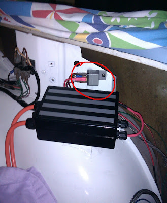
This is the 12 VDC to 240 VAC inverter that runs the motor fan. (They could not supply a 12 VDC version way back when I ordered the motor.)
The inverter is mounted where the old ignition coil used to live.
I used two peices of aluminium angle that were offcuts from the rear battery tray and ran a peice of 2 mm aluminium over the top. The inverter sits on a piece of black neoprene rubber with another small strip under the aluminium that loops over the top.
Another minor problem solved. When I opened any door to the wind-stop position then closed the door again it made a sound like a gunshot. The door wind-stop rivets had to be drilled out when the car was re-painted and the bolts that they were replaced with were too loose. I reemed them out to 7.1 mm and fitted uncompressed stainless steel rivnuts (nutserts). A nice clean close now with almost no sound.

I can kind of see why. After pulling the trim off the passenger side it revealed that the wiring has missed the channel allocated for it and been glued below it by the trim adhesive.

The result is that the wiring was too short to go around a corner and was pulled tight across an edge of metal.
The purple/white wire is the door switch wire for the interior light. The metal is sharp where the wires drape over the top.
It would not have been too long before the interior light was doomed to flicker on and off of it's own free will.

The cover panels have been re-fitted to the firewall. The remaining hole is for the heater wire cable gland.

12 Volt battery mounted.
With battery. The battery is very secure - surrounded by rubber. The packing strap may be enough to hold it in. You can see the red rubber to the right of the battery with a 10mm hole ready to finally secure the top battery tray. I am using a 9 AH AGM deep cycle battery. No real reason for the deep cycle other than it was easy to get.
The red cable draped around the area in all the engine bay pictures is the BMS monitoring wire that comes from the boot.


This is the 12 VDC to 240 VAC inverter that runs the motor fan. (They could not supply a 12 VDC version way back when I ordered the motor.)
The inverter is mounted where the old ignition coil used to live.
I used two peices of aluminium angle that were offcuts from the rear battery tray and ran a peice of 2 mm aluminium over the top. The inverter sits on a piece of black neoprene rubber with another small strip under the aluminium that loops over the top.
Another minor problem solved. When I opened any door to the wind-stop position then closed the door again it made a sound like a gunshot. The door wind-stop rivets had to be drilled out when the car was re-painted and the bolts that they were replaced with were too loose. I reemed them out to 7.1 mm and fitted uncompressed stainless steel rivnuts (nutserts). A nice clean close now with almost no sound.

Subscribe to:
Comments (Atom)

