This blog documents the restoration, and conversion, of a 1965 Humber (Singer) Vogue to a fully electric vehicle. The Vogue will be powered by an 11kW(modified), 3 phase industrial AC motor, controlled by an industry standard Variable Speed Drive (VSD) or Inverter. To be able to produce the 400 volts phase to phase the VSD will need about 600 VDC of batteries. A big thanks to the contributors on the AEVA forum: http://forums.aeva.asn.au/forums/

Friday, September 17, 2010

The Real Fuse/Contactor Box

And here is the real one. Finished last night. This is the -ve version (for the boot). The +ve version has the contactor around the other way as the contactors are polarised.

The large cable glands on the left are for the orange traction cable, the smaller glands are for 12 V control and 600V low current.

Tuesday, September 14, 2010

Fuse and Contactor Boxes

One of these has to go in the boot and one in the engine bay.
I have already bought the boxes and have all the parts but I won't finalise them until I actually physically put some parts in the engine bay. The layout of the cable glands is quit critical as I don't have much room.
Anyway - this is what they will look like - clear covers too!
You can see this box on the left in the previous post with the engine bay sketch.
The real thing won't be nearly as colourful unfortunately.

Monday, September 13, 2010

12 Volt System for Headlights etc.

Someone asked me last week what I would be doing for the 12 Volt system in the Vogue. Would I just have a big battery that I charged when I charged the battery pack.
Well, that's an option and one that some conversions use.
I don't like the idea much because I can imagine sitting comfortably in peak hour traffic on a cold, rainy night listening to great music (with no engine idling over), when the 12V system starts to fail.
So the option I have chosen is the have a small 12V battery - say 7 to 12AH sealed - which has the primary function of closing the main traction contactors, then have a DC to DC converter that runs the 12V system from the main traction batteries. The DC to DC converters are usually quite expensive but the Vogue's 600 VDC pack can be easily tapped in the middle to create two 300 VDC voltage sources. Since 300 VDC is very close to 220 VAC peak voltage, an easy source of these converters is eBay Switch Mode Power Supplies.
 A risk I had to take was that the supplies went into "fallback" mode when they encountered a large current - the headlights switching on. The ones I bought were OK - they deliver 20 Amps into a near short circuit. They also adjusted up to 13.8 Volts with no problems.
The only problem with these supplies is their open construction - and the small fan which I didn't want (circulating dust).
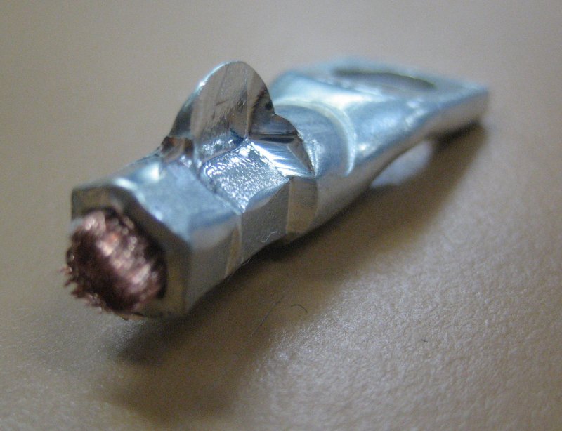
So a bit of searching "upstairs" at work found this part of a freight train radio system power supply.

A bit of work with the angle grinder and an aluminium cut-off wheel.
Then some countersunk screws, a few holes and tapped threads and another bit of 2.5mm aluminium, then a long search for sealed plastic cases the right size and...

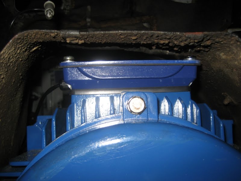
The finished product. Splash and dust proof - no fan - just a large heat sink. They are bolted back to back with the lids on the outside to allow wiring. A single unit delivered 13.6 VDC at 10 Amps for 30 minutes without excessive heat build up. The outputs of the two power supplies will be paralleled with a suitable length of wire from each one's output to ensure reasonably equal load sharing. It's also reassuring to know that one of these can power the entire electrical system in the Vogue on that rainy, cold night. There would be a slight mis-balance in my packs but that's better than having to be towed...

Here is the latest Google SketchUp of the engine bay components. The DC-DC converters are on the right. I really did draw this before I made them (but after I found the boxes and the heat sink).
This is one of two engine bay layouts I am deciding between. The main difference is that in the other one, the controller is sideways to get better airflow. This layout only has 30mm clearance in front of the controller.

Monday, September 6, 2010

Motor Mounted for Good!

This is a kind of repeat of this post showing the motor going in but the motor is back in the car - for good (fingers crossed).
The terminal box is fitted and all the high current wiring is attached.

The black wire trailing out the side of the main terminal box is for the embedded motor temperature monitoring. The grey wire emerging from the small terminal box is for the shaft encoder. The unused black cable gland is for the motor fan wires.

View from the front of the car. I regret not putting the fan wires on - I'll need a cut-down screwdriver. I didn't want to attach it because the wire already has the correct connector on it, but I now realise I'll have to connect it before the battery cradles go in.

View from the engine bay, taken by poking the camera into the transmission tunnel. Not much clearance. The problem is the far left terminal cover bolt. I ground it down to about 1.5 to 2mm thick and used a star instead of spring washer. At least you can see daylight over it.

As with the previous photo, I couldn't actually see this - only the camera could. This is a view from inside the car poking the camera down into the area where my head doesn't fit. The one at the right is the tight one.

I also got the battery mounts de-rusted and primed and started on splash proofing the DC-DC converters.
More later...

Friday, September 3, 2010

Battery and Motor cable has Arrived

The decision of which cable to get, and purchasing of battery "traction" cable has been a lot easier than I had thought. Assuming about 100 Amps maximum for battery current (I might peak 115 later with the upgraded controller), I have decided on 10mm2 cable. This cable is rated at about 1.9milliOhm per meter (at 20 degrees C) so for the 10 meter run to and from the boot should result in only a 2 Volts drop at 100 Amps. With a 600 Volts system, that's not much.

I have purchased a double insulated very flexible 10mm2 welding cable from Arrid. Tycab ZDU132202. This was just under AU$2 per meter with $17 shipping. (It's a good range going up to 120mm2). I estimated I'd need 30 meters (using Sketchup) but since it was fairly inexpensive I bought 45 meters in case I decided to do a double run to the boot (trunk) packs.

I had already got cable lugs from the ToolBoxShop in the UK and a Crimping tool from eBay - hex crimp, double action with switchable dies. (The tea towel is so I don't scratch the glass-top table I use for taking photos.)
 
Amongst others, the crimper has a 10mm2 setting and a 16mm2 setting. First I tried the 10mm2 setting - too tight! The metal has to go somewhere - it went up!
I also tried the 16mm2 setting - too loose. (The crimp closer to the wire is the 16mm2.)

 
Well Goldilocks - what to do now. I set one side to 16mm2 and the other side to 10mm2. The result was a good crimp.

I couldn't help it - I had to heat shrink it! The total diameter of the cable is 9.3mm and the copper core is only 4.5mm so it looks like they are over-crimped but I'm pretty sure they are OK.

These are the three motor cables ready to connect to the motor terminal box this weekend and get the motor back into the car. Most likely I won't be able to get at the connections once the motor is back in position.
 

Thursday, September 2, 2010

Battery Charger Isolation and Fuses

To charge my 12 battery packs I have 12 x 3 Amp chargers. There are two reasons why I can't simply connect the chargers straight to the battery packs and leave them that way.
1. The chargers draw 6mA of current from the packs when connected and the chargers are not switched on.
2. The chargers have a fuse in the positive lead but not the negative lead.

Why 6mA of current is unacceptable is that this current will gradually drain the batteries when the Vogue isn't in use - not much but enough. Six milliamps per hour adds up to 0.144 Amp hours (Ah) per day. Over 1 week that's 1Ah and that's 5% of my pack capacity. So I choose to isolate the chargers from the packs using 2 of 3 Amp diodes per charger.

Why do I care if the chargers are not fused in both leads? This has to do with the voltage at each end of my 600 Volt pack. If we assume for the moment that the pack centre will be connected to the car chassis (ground, and it may not be) then each end of the pack will be at +300V and -300V respectively. Since the packs can deliver well over 1000Amps momentarily, if the little silicon insulation washer in the charger breaks down then the wires to the charger would vaporise. I don't want a fire, so I'll fuse the negative lead as well.

This is the bundle of bits to build one of my 210mm long fuse and diode charger connections. I have chosen a type of connector used in the RC fraternity called a "DEANS" connector. They are gold plated with a spring steel backing on the pin to ensure great contact. They are rated at 30 Amps - you can see it on the far right of the picture. I make the connection finger and splash proof with a rectangle of fairly heat-proof plastic wrapped around it  with heat shrink covering it. There are LOTS of pieces of heat shrink involved.


The final products. The 6mm lugs go to the battery pack and the other end plugs into the wire emerging from the charger.

Eight finished, 4 to complete. The copper heat sinks are from an old copper fire screen that became available when we fitted a chimney damper in the house. I polish them and file the rough edges off before using them. Every wire is heat shrunk to provide double insulation. I will double insulate the diodes where they can be touched by humans (only a few packs will be "touchable").


For the technically minded the heat sinks settle to 40 degrees above ambient when delivering 3 Amps for an extended period. The heat shrink appears to dissipate enough heat due to the close contact with the copper heat sink.