This blog documents the restoration, and conversion, of a 1965 Humber (Singer) Vogue to a fully electric vehicle. The Vogue will be powered by an 11kW(modified), 3 phase industrial AC motor, controlled by an industry standard Variable Speed Drive (VSD) or Inverter. To be able to produce the 400 volts phase to phase the VSD will need about 600 VDC of batteries. A big thanks to the contributors on the AEVA forum: http://forums.aeva.asn.au/forums/

Wednesday, March 30, 2011

Start/Run Control Circuit Diagram

The control interface to the Vogue has changed a bit over the past two years. It has got simpler and simpler.
Here is the almost-final circuit.
If the user tries to start the car with the Forward/Neutral/Reverse switch in either Forward or Reverse, it beeps at them. The contactors will only engage in Nuetral.
Also the contactors will only engage or stay engaged if the Intertia switch, Charger lockout and Manual disconnect are all closed.

Text in brown is wiring within the 8 way cable from/to dash to motor controller. Text in blue indicates existing wires in the Vogue loom.The multiple wires from dash to engine bay is because the SW60 contactors are on the passenger side of the engine bay whereas the DC-DC relay and EV200 is on the driver side.

(Note: Image updated 29th April 2011 and again 11th May 2011 when the Start/Run relay was relocated to the Engine Bay)

Tuesday, March 29, 2011

Engine Bay Wiring

I'm pretty much ready to finalise the Engine Bay control wiring so I thought a bit of planning would be good. I have only fleetingly thought about this in the past but now I have allocated existing and new wires.
here is take #1. I have left the detail of the control wiring to the Motor Controller out for now. The wiring route is indicated though.
Brown wires are existing high-current wiring. Green wires are existing instrument wiring. Blue and Red wires are new.
The purple cable is a shileded wire (plus one conductor) for the battery pack current sensor.

The diagram shows the Engine Bay of the Vogue with the front of the car at the bottom. Where the wires go from side to side across the car is the dashboard side of the firewall. For instance the Start/Run relay is in the cabin behind the dash. Click on the image for full size.

LATER EDIT: I also have not shown any high voltage wiring nor some connections to the controller. For instance accelerator, motor shaft encoder, motor temperature monitoring and BMS monitor wiring.

Monday, March 21, 2011

Dashboard Progress

The dashboard has been progressing on and off over the past year and a half. Over that time I have sanded back the woodwork, filled, coloured and sprayed with Marine clear. I have also cleaned up switches and fixed bad contacts, resprayed the metalwork and cleaned up the chrome surround.
The Forward/Neutral/Reverse switch is also mounted.

To put it in perspective here is the original. It looks better in the photo than is actually was. There were lots of cracks and blemishes. You can see the finish lifting off the glove box cover on the far left of the picture. It was like that in lots of other places but to a smaller extent.


The "Rootes Group" insert seen here (which filled in the clock hole as it was seldom fitted) is now dark blue, semi transparent and back-lit.


The Oil pressure gauge (to the right of the Rootes Group badge above) has now been replaced with three small push buttons - Trip reset, Up and Down (for contrast etc.). The Amp meter (far left gauge in original) is now a colour LCD temperature gauge which will tell me the engine bay battery pack temperatures.

Here is the fully restored dashboard without the speedo cluster.
Note that the "Lights" switch has moved to the far left where the choke was. The old hole vacated by the "Lights" switch now has the Forward/Neutral/Reverse switch. I have not changed any holes or mountings in the dash.

Close up. I have also changed the indicator lights for the hexagonal version used in the slightly earlier Vogue. I prefer them.
The heater controls bezel covers that darker section.

The reason the speedo is missing in the above picture is that, like most rear wheel drives cars (not all), the speedometer is operated by a cable running off the gearbox. I've removed the gearbox!
The small cable coming out the side of the tail shaft extension housing is the speedo cable.
(Later edit: Added red circle - I hate it when you can't easily see what someone is talking about!)

So I will be running a speedo that is driven from an electronic signal from my controller that tells me the motor speed. Since the motor is attached firmly to the tail shaft, it tells me road speed. It does mean doing a digital speedo and I briefly fooled around with the idea of driving the old one with a stepper motor or synchronous motor but it plain got too hard. So an LCD display it will be - since that is what I do for a living it should be no problem.

The original speedo mechanism removed from the housing. A mechanical wonder. Still working perfectly after 45 years (except for the faded ribbon). Note the trip reset shaft that is responsible for the hole in the perspex front seen a few pictures down.

I am now working on finishing the Speedometer cluster. The Speedometer, ODO, Trip, State of Charge (fuel gauge) and Current meter software has been written and tested. I currently have all these on one 60 x 50 mm display but they will be spread out across the three displays when finished.
The software is based on one of our company's transceiver control heads so I had a running start.


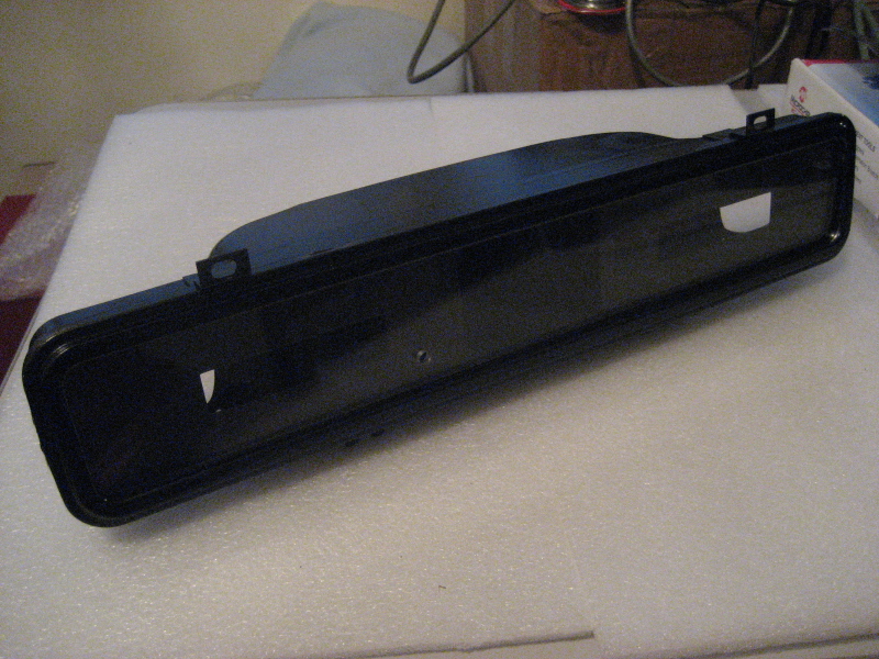
This is the original housing with the mechanical parts (above picture plus two gauges) removed  - then a coat of black paint.

I have made covers for the two oval holes in the back that were left by the old fuel and water temperature gauges.


The big hole in the centre back (picture below) will have a DB15 connector for the cluster wiring. I'll just plug up the dashlight holes.


I made up an aluminium 'L' section with holes in the front for LCD displays.
I'll be using a 128 x 64 pixel 60 x 50mm monochrome reflective LCD for the actual speed display - so direct sunshine won't be a problem.

Two 16 character x 2 line white on blue LCD displays go at either side of the speed display.


The metal frame in the foreground was made from the old front panel of the original speedo.

It's funny how some things annoy you. In this case, I was annoyed that it cost $80 to have this water-jet cut. My nibbler just wouldn't have done it.


Some captive nuts so I can secure the 'L' frame into the housing. I was going to use "nutserts" but the 3mm ones didn't pull in properly (I think I overdrilled the holes) so I used these brass ones that you secure with a centre punch and a hammer.


The whole lot assembled without the displays. The hole in the perspex was for the old mechanical trip reset.
About the only thing I can think of to put there is a 5mm LED - it fits perfectly.

Tuesday, March 15, 2011

Accelerator Mounted

All done. I should show the nutserts without the pedal. I might take another picture and just edit this post.
I haven't used spring washers because I need to remove it and drill a hole for the bonnet release - probably just above the pedal. I LOVE nutserts! I squirted Fish Oil through the lower hole after I drilled it  - plenty enough to pool at the bottom of the panels to stop the drilling swath causing rust.

Sunday, March 13, 2011

Accelerator Mounting Idea

I asked around for ideas at work this week and came away at the end of the week with one of our "Nutsert" tools (on loan only).
The plan is to drill two holes in the firewall where I can't get at the other side and use these blind-insertable nuts. I played around with an M4 version and it's pretty solid once it's in.
Before insertion.


"Other" side.


Front (insert) side.

I will have to figure out a way to get a slight angle on them as the pedal mount wants to be angled down a bit.

Tuesday, March 8, 2011

More Accelerator Pedal Stuff

Well it turns out that there is no way that the VW pedal will fit. It wants to be mounted halfway through the fresh air duct.
Seeing as how the Audi pedal has a metal arm, it follows that it can be modified. A colleague at work does a bit of welding so I asked for help. He had a great idea that I should place it in position and make some V cuts then bend it to how I wanted it. He would then do some fillet welds to fill the V cuts. I didn't quite do what he asked (V cuts too small) but I made it fit perfectly and he expanded my tight little cuts and welded it up. I even got a free paint job (thanks Jens).
Here it is roughly in place with one bolt holding it that I drilled for the bonnet release cable which now has no home - (next problem).

 Another perspective. You can just see the rejected VW pedal in the right foreground. I would prefer the accelerator pedal being closer to the floor than the brake pedal and I might do a little better than shown if I forgo some pedal travel, but it's pretty close.

Now to figure out how to secure the bottom when I don't have access to the other side of the panel (twin panels on mudguard), and to devise a new position for the bonnet release (see just above old accelerator in the previous post).

Tuesday, March 1, 2011

Accelerator Pedal Mounting

Some time ago I completely ripped out the original accelerator system in the Vogue with the intention of replacing it with a modern "fly-by-wire" pedal. That hasn't been as easy as I thought it would be. I have been fussing with ideas for a week or so. I actually have two pedals, one from an Audi A4 and one from a VW Polo. I bought the Polo one after the Audi one because it seemed a bit more compact.

This is the Polo pedal. This is most likely the one I will use. (Later edit: I didn't - I used the Audi one - modified a little.)
And this is the Audi pedal. The rod is too long and the pedal is biased about 100mm to the right of where it mounts.

One of the problems is that the Vogue has two metal panels in the front mudguard area - inner and outer. The red circle is where I have to add an extra bolt but it will not be accessible in the wheel area on the other side. (Very old picture shown here.)
More as it evolves...