This blog documents the restoration, and conversion, of a 1965 Humber (Singer) Vogue to a fully electric vehicle. The Vogue will be powered by an 11kW(modified), 3 phase industrial AC motor, controlled by an industry standard Variable Speed Drive (VSD) or Inverter. To be able to produce the 400 volts phase to phase the VSD will need about 600 VDC of batteries. A big thanks to the contributors on the AEVA forum: http://forums.aeva.asn.au/forums/

Wednesday, August 31, 2011

Interior Cleanup prior to Trimming

Since we are nearly ready to start trimming the interior I did a job today that I have been putting off. Cleaning the old adhesive off the interior panels.
Googling around the net I had discovered 3M Citrus Adhesive Remover - I couldn't get that! The man at Bunnings (hardware store) suggested this stuff "oomph". So armed with that, some small wire and fibre brushes and a bag of old socks, I set to work.


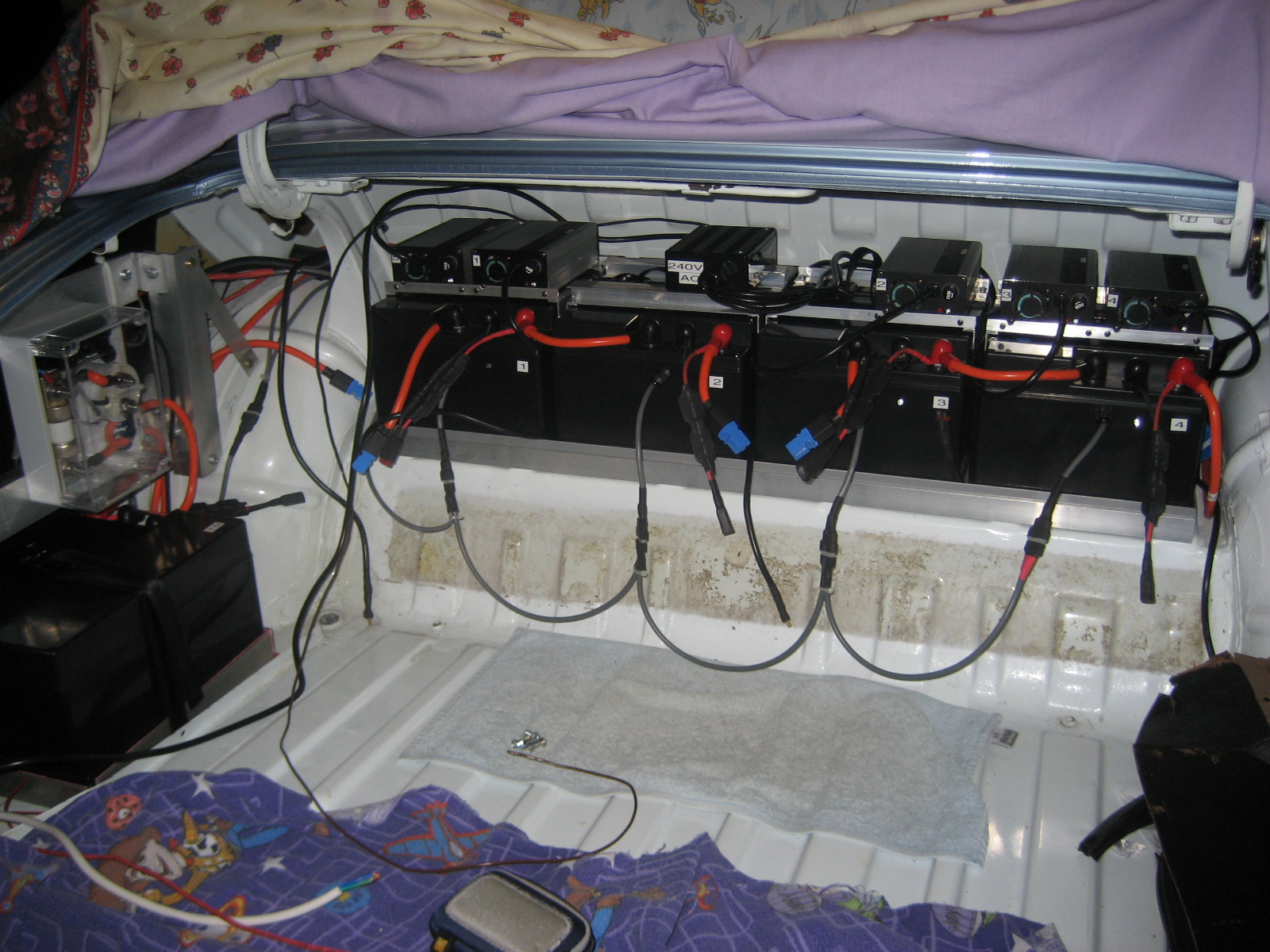
 This is one of the pictures I took with the old carpets in the car so we knew what the layout was. Note the old adhesive on the panel under the door.


Half cleaned. It took a LOT of rubbing.


 Drivers side done. I haven't decided whether to clean the doors or not - I won't be using glue so I don't need them clean (unless I glue the waterproof plastic sheeting on which this Vogue was curiously missing) - we'll see how I go.


I finished around 5:30PM - it took the whole day. I did remove, clean, and reinstall the headlight dip switch and cleaned adhesive from inside the boot too. I got through about half the socks.

Monday, August 29, 2011

Getting Ready for Door/Window Rubber Installation

A few years ago we replaced all the pinchweld (the stuff that goes around the doorway of your car so you don't scratch yourself on the body seams) and all the door rubber in our 1967 Humber Super Snipe. In preparing to do the Vogue I wanted to have better tools as cutting the rubber on strange angles was very difficult - involving experience I did not have. The Vogue will be even more difficult as I have to make the rubber seals for the rear 1/4 light windows which involve angles other than 90 degrees.

In a brief visit to one of the auto rubber places last week I was impressed with the hand shears the guy used to cut a sample piece of rubber moulding for me. He indicated that they were quite difficult to find and his were nearly shot - so I went looking.
I bought this on eBay last night.


PVC CUTTER SET - PLASTIC CONDUCT - TILE TRIMS - RUBBER

NS-190-608 Trim Cutter Set 5 Piece Tradies 

Multi application cutter with 5 interchangeable anvils.
Cuts flat, round, 90 degrees and multiple angles.

Friday, August 26, 2011

Charger Sequencer Installed and Rear Pillars Painted

The Charger Sequencer is installed. I haven't quite finished wiring (note floating earth wire) as I can not finalise the inlet wiring until the three pin plug is mounted in the fuel cap - but the eBay 16A RCD/MCB handled the load fine. I can't say the same for the temporary 0.75mm cord I used for a few minutes until it nearly cooked. The 1mm inlet lead I have put aside with exactly the correct size plug to fit in the fuel filler was fine.
Finishing the headlining was delayed when we realised that black paint on the two pillars just behind the rear doors was pretty bad. Spraying them was too difficult at this stage so Laurel thought that vinyl covering was the go (I had just enough left over from the front). I was reluctant to put vinyl on them because I thought it would complicate the 1/4 light window installation (the triangluar window just behind the pillar). 


We finally decided to give brushing them a go and if it didn't work then use the vinyl.
I sanded them back with 800 wet and dry and put a generous single coat of Black Gloss Enamel on them. The camera can't show it but it looks like they are plastic coated - no brush marks.

Thursday, August 25, 2011

Headlining Fiddling

The headlining is taking a bit of time and "fiddling" to get right. It's working out well but minor things like realising that the rear pillars just behind the rear door were not painted have slowed things down.
Here is a picture of how we plan to finish the headling at the top of the front windscreen pillars. It's the same way that the vinyl headlining was finished.


We have also run some fabric along below the rear windscreen and glued it in ready for the headlining to be glued down.

Sunday, August 21, 2011

Windscreen Pillar Vinyl


(This post restrospectively added on 29th Aug.)

The vinyl covering the front windscreen pillars was in pretty bad condition so we took the opportunity to replace it.
The dashpad restoration guy sent me down some spare vinyl (the same as the stuff covering the new dashpad) for exactly this purpose.

Plus a couple of boxes of foldover clips from the local office supplies.


The old piece and a new piece of vinyl cut roughly to shape 


I didn't actually use the heat gun while the clips were on but you get the idea. Heat gun on low and just enough heat to form the vinyl.


All glued and clipped up.


"Can I help? I won't steal any vinyl!". Yeah right.

Tuesday, August 16, 2011

Headlining Back In

One of the problems when we fitted the new headlining (see this post, and this post) was that the 15mm acoustic foam that I glued to the inside of the roof was just a bit thick. We were unable to properly get the bows into position and have the fabric (listings) drape over them without pulling to one side or the other.
So I did a bit of work this weekend with Laurel's fabric cutter and a scalpel.
First I draw chalk lines on the insulation from left to right across the roof where the bows sit.
Then the fabric cutter was used to slice about halfway through the foam.
Next some careful scalpel work...
The result is these channels.
During this time, Laurel was inside repairing the ends of the listings where we had cut them back too far the first time we installed it almost a year ago. If we ever do another suspended headlining, it will be a lot easier (if we remember what we did wrong that is).

The bows were heaps easier to get in and the listings could now be positioned to let the headlining drop correctly.
It's currently being held in by lots of these clips.
A bit grainy because the flash washed out the fabric (if I used it) but you get the idea. It needs just a tiny bit more work to get the wrinkles totally out.

I have to glue the vinyl onto the front pillars before the headling goes in. I also have to cut a piece of this same fabric for across the back between the rear windscreen and the rear parcel shelf, then the headlining can be glued in for good. The front pillar vinyl is currently on my workbench being "flattened" after being rolled up for about a year.

Friday, August 12, 2011

Battery Pack and Traction Cable Placement

A bit of retrospective documentation here.
I have had this diagram since I decided on Lithium batteries but since the blog is my documentation I thought I'd better post it. The battery pack numbers are important as I have documented history on each pack as they have been modified and charged. Click on the image for a better view.
(Diagram updated 12th Sept 2011)

Rear Chargers Installed

Simply placing the chargers in their mounting brackets on the rear battery packs didn't turn out so "simple". The 240VAC termination box was about 2mm too narrow so had to be partially disassembled and the holes filed. Then the straps for 3 out of 4 of the packs were in the wrong way around (it has to do with camlock buckle placement). Not wanting to remove all the packs then crawl under the car and unmount the main tray, I used the safety pin and nylon cord approach to carefully remove the strap while pulling the cord through - then pulled the strap through the other way.
Anyway - chargers in position.
Now to figure a way to route the wires so it looks reasonably tidy.

Wednesday, August 10, 2011

Rear Charger Mounting Progress

I originally intended the wires to the mains inputs on the chargers to be magically terminated somewhere at the back of the packs but a clean, neat system didn't work out. So I made one more pack-stradling mount (slightly different to the charger ones) and put a termination box on it (black box in the middle).
This is the order that they will be installed on the battery packs in the boot.
I managed to get an hour or so last night to finish the last mounting frame and wire up three of the chargers.
Just a few more wires and they can be strapped in.
This was the original sketchup. I see that a charger has moved from the left to the right of the middle mounting frame. The direction I installed the battery straps tends to dictate these things. The buckles take up room and the straps would be difficult to change. They are easier to tighten in one particular direction.
Actually that is why the two-charger frames are on the outside packs - it's so I can put the buckles down the sides of the packs.

Tuesday, August 9, 2011

Speedo Installed in Dash

I assembled the speedo into the dash a couple of weeks ago but forgot to put up a picture. The windscreen washer and heater control are stll not mounted but only because they are not convenient until the dash is ready to go in the car - and that's after the dashpad and windscreen.

Sunday, August 7, 2011

Rear Charger Mounting

With sore throat and head cold symptoms I braved the cold garage yesterday and cut up the aluminium for the rear charger mounts that I envisioned back in this post.
I started with three 1 metre long pieces of 20mm x 12mm x 1.6mm aluminium angle.
With suitable audience, the pieces are ready for assembly.
I built one first to check I hadn't made any weird mistakes. Here it is upside-down with 1.6mm neoprene rubber glued to the load- bearing surfaces.
Then into position with it. It is a great fit over the pack and is quite difficult to slide even without the strap. The strap will thread through easily, over the side section, between the chargers and the pack. A bit of a pain to get on though so I haven't done it until they are all ready.
Now to make another two of them.

Wednesday, August 3, 2011

Replaced RCD


I weakened. Much as I like to use as much recycled stuff in the Vogue as possible (provided it's reliable and safe), the 40 Amp RCD and 20 Amp Circuit breaker just take up too much room in the Mains box. I have ordered a 16 Amp combination RCD / MCB from eBay. Similar to this 10 Amp version. It'll give me  a lot more room to play with.

I hope it arrives for the weekend.

Tuesday, August 2, 2011

Mains Charger Power and Sequencer

With the Vogue now running it's about time the mains inlet was finalised so it can be charged easily.
This is a bit more complex than just connecting the 240 VAC mains plug to the chargers.
The reason is that I have 12 chargers. Each one is specified as drawing 30 Amps peak inrush current when switched on. It follows that all 12 would draw over 300 Amps inrush and I do not want to become unpopular when I want to pick up a get-me-home charge by blowing someones circuit breaker.

So - I have a system that switches on the first 4 chargers, then waits 2 seconds and brings up the next 3, then 2 seconds and the next 3 then 2 seconds and the last 2 chargers switch on.
I call it the Charger Sequencer.
The box, circuit breaker and RCD in this picture were "skunged" when the airconditioning system was changed at work. Since I have them, I'll include them. (The box already has a mounting place in the Vogue as you can see in a previous post that included pictures of the boot/trunk.)
The cable gland on the bottom is for mains inlet while the two white ones at the top are for front and rear chargers.
Here is a closer look at the Charger Sequencer PCB. The power supply is an 800 mA, 5 VDC phone charger. The relays came from a dismantled piece of test gear at work too (old ATE)!
It should be mounted and wired by the end of the week ready to go back into the car. You can see I have already cut up the piece of aluminium to mount the board.

For those who want to know how it works.