This blog documents the restoration, and conversion, of a 1965 Humber (Singer) Vogue to a fully electric vehicle. The Vogue will be powered by an 11kW(modified), 3 phase industrial AC motor, controlled by an industry standard Variable Speed Drive (VSD) or Inverter. To be able to produce the 400 volts phase to phase the VSD will need about 600 VDC of batteries. A big thanks to the contributors on the AEVA forum: http://forums.aeva.asn.au/forums/

Showing posts with label controller. Show all posts

Friday, April 19, 2013

Second Week as Daily driver

Not much to report about the Vogue other than I have driven it every day this week with no issues. I logged data from the dashboard to and from work on Thursday and some interesting things came out of it. The major one being that my acceleration up to 4 km/h is slower than 4 km/h to 70 km/h. This has to do with the controller de-rating it's output below 5 Hz.

This isn't a hard problem to get around - in fact by changing it's "carrier" or PWM switching frequency to 4 kHz the problem goes away - but it's too noisy. I currently use 16/8/2 kHz auto switching where the controller auto-changes based on motor current but it appears to have an idiosynchrosy that retains the 16 kHz current limit even when it's auto switched to 2 kHz. It looks like I'll have to add some function blocks to switch it over.


My logging laptop on the passenger floor.

A timer on the carport 15 A power point would be handy too. I currently go out each night at 11PM to turn my chargers on. I have bought a 16 A timer in a nice outside enclosure but I have to add some leads and install it. Soon....

I'll post the daily economy figures for this week during the weekend.

Sunday, March 17, 2013

Rotor in, Motor in

I have re-installed the rotor back in the motor, fitted the shaft encoder and re-fitted my IP65 spray can lid. The only silicone I had was the high temperature stuff that I used on the heater core. That worked nicely.

I'm glad border adhesive is useful for something (weight). After the huge trouble we had stripping it off my daughter's bedroom wall we swore we would never use it again.

Since I had to wait a day for the silicone to set, I turned my attention to the chargers and controller tray. I am going to drill out all the 4mm holes and use M4 rivnuts so that I can get stuff off the tray without having to remove it (the tray). I ran out and bought a 6mm cobolt drill (for stainless steel - it works really well) and tried to use a manual method to insert the rivnut - no good. I'll take the tray to work and see if I can use the tool there. So the tray is in the boot of the Super Snipe.


The blue circles are some of the 4mm holes - the red is a 6mm hole I have drilled out.
The DC-DC block (still on tray) is another matter. It's held on with M6 bolts through the bottom from inside the case (nuts underneath). It isn't impossible to get off without removing the tray - just difficult.


As of Sunday afternoon, the motor is back in the car.
It took me and William about an hour of messing around with a jemmy bar and many blocks of wood to get the rear of the motor to a height where I could get the Jack under it. From there it was relatively easy.

I have about half the chargers (six) left to modify. I have to change the current shunts in all the chargers to finalize my modifications for two current settings - 3A and 180mA. I have ordered some shunt wire but it's not due for a week or so. I can still finish installing the controller tray since the rivnuts will allow me to install the chargers afterwards.
Daughter board for current switching shown circled.

My two spare chargers (where I tested this modification) didn't need the shunts changed - they were 12 milliohm. The twelve chargers in the car appear to have anything from 6 to 9 milliohm shunts which makes the low current setting too high - hence the shunt change.

The modification allows the charger to charge at 3 Amps then, when the current drops to less than 300mA, the charger switches to 180mA Constant Current - which is the value that the rudman regulators (cell bypass resistors) in my packs are set. It'll means that charging the car is a set and forget operation - which is as it should be.

Tuesday, September 18, 2012

Programming the Vogue

The motor controller in the Vogue is made by a German company called Lenze. They offer a free programmer that runs on a PC called Global Drive Control or GDC Easy. It has some limits to functionality, mainly that it can not be used to visualise the entire configuration. There is no limit to what you can actually do - just how you view it. I would LOVE the full blown GDC (Lenze, FCR - anyone?) but it's a tad expensive for a non-factory application like this. GDC also lets you change most parameters without loading the whole configuration so you can play with values quickly and easily and note the results immediately. In many cases you must disable the controller to change a parameters but that means just switching the Forward/Neutral/Reverse switch on the dash to Neutral in my case.

I use Laurel's old Thinkpad T40 for general Vogue programming. I have the dashboard software development system, GDC and a simple serial terminal program on this laptop for recording the dashboard output (if I decide to log a trip). Unfortunately it's battery isn't so healthy (kind of ironic for an EV tool), only being good for about 40-50 minutes so I need to attend to that.

Here, the Vogue is on axle stands while I fiddle with some live parameters.


Wednesday, September 12, 2012

Speedo Inaccuracy Explained (mostly)

The tyres I plan on using are 185/65R13. With the Vogue's 3.89:1 differential ratio, that works out to be 41.48km/h at 1500 RPM. In the speedo software I divide motor RPM by 36 (41.67 from 1500 RPM) and round up to the nearest integer so it should show 42km/h.
I placed the Vogue on axle stands last light and locked the controller's maximum motor speed to 1500 RPM.

I set the PC to monitor various controller variables including actual motor RPM.
Flooring the accelerator gave me 1499.9 RPM on the PC monitor and 42km/h on the speedo in the car.

So all the calibration and calculations are actually correct - so why does it show 67km/h when we are doing 60km/h?

About the only thing left is the diff ratio - but that can't be wrong - can it?
Historically, the Mk3 Vogue sedan was shipped with a 3.89:1 diff. The earlier Mk2 has a 4.22:1 then later in the run changed to 3.89:1 - or so the rumors say.

The 3.89 to 4.22 would make about an 8% difference to speedo ready. My 67 to 60 is around 10 to 11% - but it's close. The current tyres on the car are 175/70R13 which are ever-so-slightly larger than the ones I calibrated for but it's not much (this should slightly counter the different diff.).

Back to diff. ratio. When I bought the Vogue it had been built from three donor cars. We know one of them was a Vogue Sports because I have the boot lid and badge, BUT, the Humber Vogue Sports never shipped as a Mk3 in Australia, so the boot lid is from a Mk2 - might the diff. be as well?
(The Sports did not sell as a Humber in Australia because all Mk3 Humber Vogues were upgraded to the Sports Alloy Head Rapier spec. motor - no need for a Sports.)

I'm very happy with a 4.22:1 final drive ratio - I had even considered chasing one up so that's good.
So a speedo software change is in the works.

Tuesday, September 4, 2012

I Have Regenerative Braking

Some help from AEVA members and regen. braking is now working (emoticon with red face). The Vogue is still on axle stands but a quick test this morning showed power going back into the batteries and the rear wheels coming to a pretty quick stop when I lifted my foot off the accelerator pedal - no thump either. I had to allow torque to go negative for regen. I went to a lot of trouble to NOT let that happen - picturing a ride on lawnmover with forward/reverse control on the one pedal.

I have kind of come to the conclusion that the differential probably has no oil in it. I don't mean low - I mean none. The car sat in the back yard for about 6 years, then 3 years getting restored and electrofied - and I know the diff leaks, and not just the seals, I think it leaks out a faulty seal in the drain plug as well....
The rumble of gears running in a hollow diff housing is unmistakable (this only became obvious when running the car in the garage on axle stands). Fortunately I haven't driven the car very far in the last decade - since I checked the diff oil. I won't be running it again until I fill it. I have to pull the rear axles at some stage in the next year so I won't go overboard at this stage - I'll just fill it.

Wednesday, January 25, 2012

Traction Battery Pack Schematic

Something I haven't included in the blog to date is the Traction Battery circuit.
The little blue connectors that connect some sub-packs to others are Anderson PP75 connectors. They are heatshrunk so as to provide finger-proof disconnects. When the "Traction Enable" is off, the entire pack is isolated from the Controller, Heater and DC-DC converters.
The term "VFD" refers to the motor controller - known sometimes as a Variable Frequency Drive.

(Later addition. I see that this page gets a lot of views so I should explain that the Vogue battery pack is a 600 VDC system - which is an unusually high voltage for an EV. I have divided this into two 300 VDC "half packs" - a positive and a negative set of packs. Each numbered pack is comprised of 32 x 10AH Headway LiFePO4 cells arranged as 16S2P - essentially 16 x 20AH cells.)
(Updated 08 Jan 2014)

Wednesday, July 20, 2011

Commissioning Woes

Well the Engine Bay wiring was pretty much completed by Monday at about 4PM. Everyone stood back at a safe distance and we turned the key to 'Start' - nothing happened. A quick think and I realised that the Charger inhibit wire to the boot (so the car will not go if the charger is connected) was not connected to anything. I clipped it to vehicle ground and turning the key to 'Start' resulted in a satisfying clunk as all the contactors closed. The 12 V battery now read 13.7 volts - good.

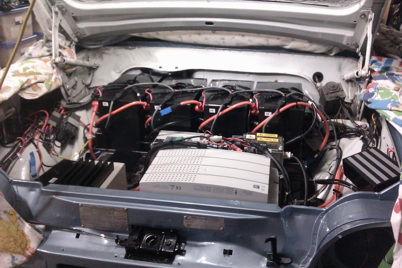
The completed engine bay.

Now the problems.
The controller has 4 digital outputs and 6 digital inputs. I need 4 of each. One digital output is used as a 24 VDC source for the 24 V logic on the digital inputs to the controller. This output appears to be 'fried'. No matter what I do it stays at 0 V. It turns out that digital input 4 is the culprit. For some reason it draws enourmous amounts of current and destroyed the output I was using for 24 Volts. I had assumed (when you assume you make an Ass out of U and Me) that the outputs would be current limited - not so - they just blow up. Anyway, I stopped using that particular input and swapped to another output for 24V and got a bit closer to everything working.

Once the above was sorted out we broke for dinner and afterwards I downloaded the prepared configuration into the controller. This is the first time I have run the controller in Torque mode and - IT WORKED!

Next problem - it would not make the motor go in reverse. I left that until I had time to think about it and review the configuration.

One final issue is that when I selected forward or reverse, both of which enable the motor outputs of the controller, I get a warning from the low 3 battery pack opto bus - the packs UNDER the controller tray. (Couldn't it have been any of the other seven battery packs?) Crawling under the car showed the the indicator light for pack #10 (the rearmost of the three packs under the trays), was going out when the alert sounded. Strangely, measuring the voltage of the pack when the problem happened showed 52.7 VDC - the same as the rest of the packs.
So 2 hours later with pack #10 removed for examination, I took this picture.

Pack #10 is now on my bench inside with the lid off. According to my modification notes (when I modified the packs), pack #10 was the only one that had clear signs of a short when it was being made. A flat washer had a quarter blown off and there was black residue on the top of the cell it was attached to (no, I didn't do it).

Now where do I get a 5 Ohm, 200 Watt resistor to use as a test load? Counting portable electric heaters now - each one is good for about 2 Amps at 50 Volts...

Friday, July 8, 2011

Chargers, Contactor/Fuse and DC-DC Mounted

It's been a pain getting everything mounted. Even though I made the hard-to-get-at bolts captive (epoxied from underneath), it still took an hour and a half to get these components mounted.
Then the thought struck me. I had always intended to make everything on the controller tray plug into the rest of the wiring so I could get it out easily - fully populated (except for the actual controller).
Why on earth didn't I mount everything first?
The reason is that the controller tray does not easily go in if the top battery tray is in - well it isn't.
Never mind - as long as I remmeber it next time I have to remove the trays. Remove the top battery tray FIRST!
Picture of chargers (right and centre), Contactor/Fuse box and DC-DC (left).
Now add the motor Controller.


I am using Anderson PPL connectors for the + and - 300 VDC (and pack centre) connections to the DC-DC and heater. Shown are the blue/white/black connections for the DC-DC convertors. (The DC-DC convertors take the + and - 300 VDC and change it to 13.7 Volts DC at up to 40 Amps to run the Vogue 12 V electrics - headlights etc.). We carefully set both of them to 13.7 Volts with a 200mA load so that they draw the same from both halves of the full pack.

Tuesday, March 29, 2011

Engine Bay Wiring

I'm pretty much ready to finalise the Engine Bay control wiring so I thought a bit of planning would be good. I have only fleetingly thought about this in the past but now I have allocated existing and new wires.
here is take #1. I have left the detail of the control wiring to the Motor Controller out for now. The wiring route is indicated though.
Brown wires are existing high-current wiring. Green wires are existing instrument wiring. Blue and Red wires are new.
The purple cable is a shileded wire (plus one conductor) for the battery pack current sensor.

The diagram shows the Engine Bay of the Vogue with the front of the car at the bottom. Where the wires go from side to side across the car is the dashboard side of the firewall. For instance the Start/Run relay is in the cabin behind the dash. Click on the image for full size.

LATER EDIT: I also have not shown any high voltage wiring nor some connections to the controller. For instance accelerator, motor shaft encoder, motor temperature monitoring and BMS monitor wiring.

Sunday, February 20, 2011

Controller Cooling Fans

During the auto-tune of the controller to the motor, the controller heat sink got to almost 60 degrees C. Clearly it was time to fit the cooling fans to the controller that had been broken off in the decommissioning from whatever factory it came from.

This is how it arrived from Germany a year and a half ago. The fans did not arrive with it so it wasn't shipping damage. The seller sent over two fans later but one wasn't the correct one. They should both be 5.6W but one was a 2.8W. I pinched a 5.6W off my other controller.


I removed some useless plastic that was the old clip-in fan mounting and added a 3 'L' brackets.


Then I made up a plate to mount the fans and added two stainless steel filters. I reversed the fans to pull air through the filters.

My fan plate is square but notice how it doesn't fit up the side of the controller due to the controller being a bit "out of square". It's just the metalwork that secures the heat sink fins to the plastic work (the heat sink is fine). I think it's better to leave well enough alone rather than strip it down and straighten it. The other controller should be the one I end up using and it's case is in way better condition.

Hopefully this should make it easy to keep clean. A vacuum once every few months. I couldn't test the fans so I'll just have to wait until I get the controller hot again.

Thursday, January 27, 2011

Controller Configuration and Window Regulators

I had a day off for the Australia Day holiday yesterday.
I removed the controller tray so that I could finalise the wiring of the lower 3 battery packs in the front.
The Charger connecting cables (made here) were not long enough for these 3 lower packs so I extended them by about 120mm.

I also did a task that I have been putting off - cleaning and re-greasing the window regulators - (for the hand operated side windows).

Finally I spent about 3 hours or more putting my custom configuration into the controller. Since the controller was out of the car I took it inside and ran it from an 18 VDC plug pack. The power section isn't active but otherwise you can do everything you need to operating it in this way.
The PC software allows you to monitor digital and analogue signals that are present internally and see them graphically on a monitor window.


I had made a couple of minor mistakes but the major time user was getting used to idiosyncrasies of the Lenze PC software.

Thursday, January 20, 2011

Vector Mode fully Stable

Due to a series of straight out mistakes I actually didn't have the shaft encoder wired up correctly.
Last night I wired it up properly, enabled it and ran the motor flawlessly in Vector mode.
Now to put in my configuration for accelerator control. I guess I'd better build the mount for the accelerator pedal sometime soon.

Later edit (so I have these documented somewhere).
The motor values I entered into the controller for were:
22kW, 2960 RPM, 100 Hz, 41.3A, 440 V, 0.78 cos theta.
Param  Value
22     88.5 Motor MaxA
23     50 Gen MaxA
81     22 kW
87     2960 RPM
88     41.3 Nom. A
89     100 Hz
90     440 V
91     0.78


Which resulted in the controller's auto-tune setting these values:
Param  Value
82     0.044
84     97.77
85     0.9
92     17.8

Wednesday, January 19, 2011

Motor Control Tuning and Stability

Getting the controller to run perfectly with the motor is becoming a challenge.
I have had it "Auto-ID" once correctly but I can not get it to tune to the motor again.
Why bother? According to the Lenze manual the drive should be re-tuned if you connect the motor temperature monitoring - which I have done. I still get a bit of motor shaking at about 400 RPM which I am trying to tune out (not motor balance - V/F mode is a smooth as silk).
A bit technical but the short of it is that I need this mode working properly if I am to implement the accelerator control I want.

Monday, January 17, 2011

Conduit and Batteries Mounted

Three weeks of holidays over the Christmas and New Year break have ended for me but there has been considerable progress on the Vogue.
I had not intended to mount the rear battery packs permanently as I was waiting for my welder friend to be available but I finally decided to use the tray I had and reinforce it with 3mm Aluminium angle. It worked out fine. The set of four battery packs are held in with 6 x 1/4 Inch high tensile bolts (straps not fitted yet.). Like all the battery trays I am doing, the whole lot are surrounded by either 5mm or 2mm neoprene rubber to stop them sliding and cushion them from some vibration.

The fifth pack in the boot. Another custom battery tray. It has the strap fitted - a camlock buckle and webbing strap rated to 300kg.


As I pulled each pack out of storage I measured the terminal voltage. Most were between 52.6 and 52.9 Volts but there was one that was only 49.6V - alarm bells. I disassembled the pack to find 2 dead cells.
(Imagine picture of 2 cells with "Dead" written on them here!) No need - here it is.

I had bought 5 spares. It took about 25 minutes to change the bad ones out and the pack was good again.


The main conduit is also installed from the rear to the front of the car. It holds the feed and return cables for the 5 packs in the boot and the 240 VAC mains charger cables for the front 7 chargers.


I placed and drilled all the holes in the stainless steel controller tray - that was fun - not!
I haven't actually mounted the chargers or the DC-DC converter (pretend alternator) as the tray has to come out again before being installed permanently.

The little box on top of the left battery pack is my 12 VDC power supply (substitute 12 VDC battery which I haven't mounted yet - or purchased). I temporarily wired the four contactors up to close when the switch on the power supply is turned on.

First power up was nicely uneventful and the motor ran well in V/F mode (a fairly "plain vanilla" mode for AC controllers). The trouble started when I performed an "Auto-ID" on the motor. Auto-ID is where a controller that isn't actually matched to a motor has to explore the motor's electrical characteristics to tune the pair together. I can not run the controller in Vector (preferred) mode to use Torque control to emulate an accelerator pedal unless Auto-ID works - it didn't.

I tried several combinations of motor data to no avail. I had a depressing night running possible alternative configurations through my mind but none would be a good as true Vector mode with Torque control.


At the end of a lot of experimenting, pack number 2 was down to 50.6 Volts when the other 11 packs were still at 52.6 Volts so I decided to charge pack #2 and balance it. It took  24 hours to balance. By this time it was Saturday morning with one day of my vacation left. I tried Auto-ID again and this time noted the fail code - ID1 which could mean "Motor too small". I changed the motor data to be a 22kW at 100Hz and IT WORKED. I quickly saved the parameter set - and wrote down the 4 results of the Auto-ID.


Sunday saw me try to catch up on 3 weeks of house chores that covered a very humid week where everything grew out of control.

Wednesday, November 17, 2010

How fast will it go?

The next question I get asked a lot is how fast will it go.
With my 3.89:1 differential, 185/65R13 tyres (that's tires to you USA guys) the motor will be doing about 4339 RPM at 120km/h. The motor is rated at 1465 RPM at 75% load and 50Hz. Since the controller will go up to 150Hz at it's most efficient switching rate (gets a bit complex here because it can actually go higher), then it follows that the motor can do 4395 RPM.
So it can go about 125 km/h.

How fast can it accelerate.
Another complex question. The peak power of the motor (around 70kW) is higher than the peak power my 45kW (peak) controller can deliver so initially the car will be controller limited. I have the parts to re-work my "other" controller to about 80kW so pretty much as soon as the car is safely debugged I will change over to the upgraded controller. They are physically identical - mounting, connections, everything.
The first graph is as it will go on the road, the second is with the upgraded controller.
To give these some perspective, the original Vogue did 0-100km/h in 17, 21 or 25 seconds - depending on where you get your information.


Thanks to "woody" from the AEVA forums for the extremely complex spreadsheet that takes everything - batteries, motor, controller, car Cd, weight, rolling resistance etc. - into consideration. Predictions from this spreadsheet have been verified on a real EV.

Sunday, November 14, 2010

Battery Tray Bottom and Controller Tray Mounting

I cut the slots in the 3mm Aluminium tray and siliconed it in. I used two of the packs to hold it down. These 3 packs will have either Gaffer tape or metal tape (middle one) sealing them from road grime. I have taped over the screw holes as well. The reason I can't use gaffer tape on all 3 is that the middle pack barely fits between the engine mounting plates - gaffer tape would peel off as I slid the pack into position.

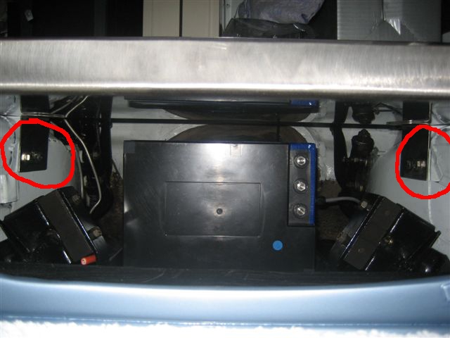
I took the plunge and drilled the holes in the chassis rail extensions that Humber so generously put there for me. The controller tray is the stainless steel tray above the red circles.
This is a view in through the front of the car where the radiator block-out panel normally lives.

Close up. We just use a stainless steel 'L' bracket. I have yet to drill the holes in the the controller tray.

Thursday, November 4, 2010

The Bonnet Closes!

Putting the bonnet back on the car this past weekend was a big deal for me. As much as I have measured and estimated, I really didn't think that the bonnet was going to close with the controller on its mounting tray.
The curves of the Vogue bonnet made it very difficult to be sure.
Note the controller poking over the top. (No the wood isn't permanent).

View from left hand side of car near passenger door. The fuse/contactor box (clear lid) has to be elevated 40mm to clear the cable glands from the DC-DC converters. The single charger behind the controller will be a stack 4 high with another stack 3 high nearer to the fuse/contactor box. A few compromises but it'll all fit.

 Alongside...

The stuff is really in there! The controller cleared the bonnet by about 35mm at the front. I put my hand up through the grill opening to check. The controller tray is supported on the wood - now I can bolt it in.

The revised layout in Google Sketchup.

Added labels to one photo 25 Nov 2010.


Thursday, October 28, 2010

Front Trays Trial Fit

A real pack and my cardboard one.
The battery packs look like they will clear the bonnet easily (heater blower is out again until this stuff is finalised).
The black tray mounts are made from 6mm steel. I haven't bolted the upper tray front mounts down yet - I'll use 10mm high tensile bolts/nuts.
This is the Front Battery tray right hand rear mount bolted to where the clutch master cylinder would have been in a manual. There is a strong plate on the cabin side of the firewall (shown in earlier posts about the refurbished brake pedal).

Front Battery tray front left hand mount.

The other side is a mirror image copy of this as the Vogue was shipped ready for left/right hand drive.


Left hand side in the engine bay.


Left hand side in the cabin - view of the firewall showing the 5mm steel reinforcing plate.

The four top battery packs (with tray) will weigh a total of 52kg so the tray (by law) must be able to stay in the car with a 20g forward force  - over 1000kg.
10g in all other directions.
The battery packs sit on and are surrounded by 5mm neoprene strips and strapped in with 300kg rated camlock straps.
You can just see the radiator hole blocking 2mm aluminium plate on the left in this photo (the grey vertical slab) - it will be flat black so you won't know it hasn't got a radiator behind the grill.
The controller tray is the lower one and isn't bolted in yet.
I'll have to pull it all out again to finish the motor and battery wiring - kind of chicken and egg.
This weekend we will put the bonnet back on (I hope) and see if the AC controller on the lower tray will clear.
(Two pictures added 26/08/2011 to show left hand side reinforcing of battery mounting on firewall.)

Wednesday, August 18, 2010

Engine Bay Layout

With both the front upper Battery pack tray and Controller and Systems tray already made I thought I'd post a quick 2D image of the Google SketchUp 3D for the engine bay.

I'm just waiting on reinforced mild steel mounts for the upper tray as the stainless steel just didn't look strong enough. They should only be a day or two away.

I have another layout with the controller rotated 90 degrees so it's symetrical on the tray but I am concerned that it will not get enough air-flow if I do that. That layout also makes it difficult to get motor cables out of the controller. This layout is my current favourite.

The bank of four chargers on the left service the upper battery packs. There are three chargers over on the right for the lower three battery packs.
The top tray is secured to the Vogue firewall with brackets attached to the Clutch Master cylinder bolt holes on both sides of the car. The front of the top tray is supported by brackets to the top of the inner guards.

The lower (controller) tray attaches to where the radiator used to mount at the front of the car. It's exactly the same width as the radiator was.
Compare this with the motor mount diagram a few posts ago - it's based on the same diagram.
Click on the image for a clearer version.

Friday, May 28, 2010

Serial Interface for Controller

I finally managed to get a serial interface for the Lenze controller(s) at a good price off eBay. Mine is a bit more scrappy than this one but it works.


Using the free version of the PC application supplied by Lenze (Global Drive Control), I can now fiddle with the 900 or so parameters in the controller more easily than using the keypad. Admittedly I'll probably only use it a half a dozen times but that's why is was good to get cheap.

It will also be useful to try different setups after configuring them in the comfort of the lounge room rather than leaning over the dashboard in the car.