Three weeks of holidays over the Christmas and New Year break have ended for me but there has been considerable progress on the Vogue.
I had not intended to mount the rear battery packs permanently as I was waiting for my welder friend to be available but I finally decided to use the tray I had and reinforce it with 3mm Aluminium angle. It worked out fine. The set of four battery packs are held in with 6 x 1/4 Inch high tensile bolts (straps not fitted yet.). Like all the battery trays I am doing, the whole lot are surrounded by either 5mm or 2mm neoprene rubber to stop them sliding and cushion them from some vibration.
The fifth pack in the boot. Another custom battery tray. It has the strap fitted - a camlock buckle and webbing strap rated to 300kg.
As I pulled each pack out of storage I measured the terminal voltage. Most were between 52.6 and 52.9 Volts but there was one that was only 49.6V - alarm bells. I disassembled the pack to find 2 dead cells.
(Imagine picture of 2 cells with "Dead" written on them here!) No need - here it is.
I had bought 5 spares. It took about 25 minutes to change the bad ones out and the pack was good again.
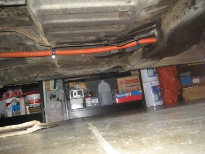
The main conduit is also installed from the rear to the front of the car. It holds the feed and return cables for the 5 packs in the boot and the 240 VAC mains charger cables for the front 7 chargers.
I placed and drilled all the holes in the stainless steel controller tray - that was fun - not!
I haven't actually mounted the chargers or the DC-DC converter (pretend alternator) as the tray has to come out again before being installed permanently.
The little box on top of the left battery pack is my 12 VDC power supply (substitute 12 VDC battery which I haven't mounted yet - or purchased). I temporarily wired the four contactors up to close when the switch on the power supply is turned on.
First power up was nicely uneventful and the motor ran well in V/F mode (a fairly "plain vanilla" mode for AC controllers). The trouble started when I performed an "Auto-ID" on the motor. Auto-ID is where a controller that isn't actually matched to a motor has to explore the motor's electrical characteristics to tune the pair together. I can not run the controller in Vector (preferred) mode to use Torque control to emulate an accelerator pedal unless Auto-ID works - it didn't.
I tried several combinations of motor data to no avail. I had a depressing night running possible alternative configurations through my mind but none would be a good as true Vector mode with Torque control.
At the end of a lot of experimenting, pack number 2 was down to 50.6 Volts when the other 11 packs were still at 52.6 Volts so I decided to charge pack #2 and balance it. It took 24 hours to balance. By this time it was Saturday morning with one day of my vacation left. I tried Auto-ID again and this time noted the fail code - ID1 which could mean "Motor too small". I changed the motor data to be a 22kW at 100Hz and IT WORKED. I quickly saved the parameter set - and wrote down the 4 results of the Auto-ID.
Sunday saw me try to catch up on 3 weeks of house chores that covered a very humid week where everything grew out of control.
This blog documents the restoration, and conversion, of a 1965 Humber (Singer) Vogue to a fully electric vehicle. The Vogue will be powered by an 11kW(modified), 3 phase industrial AC motor, controlled by an industry standard Variable Speed Drive (VSD) or Inverter. To be able to produce the 400 volts phase to phase the VSD will need about 600 VDC of batteries. A big thanks to the contributors on the AEVA forum: http://forums.aeva.asn.au/forums/
Subscribe to:
Post Comments (Atom)


No comments:
Post a Comment