Here are some photos that my son took while installing the main cable and battery trays shown in the previous post. This one is me heat-shrinking a crimp. I wonder how these crimps done in Melbourne's recent very humid week will last.

Another action shot.

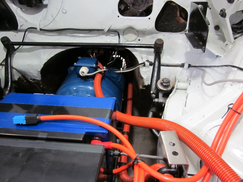
Engine bay prior to installing the controller tray and top battery tray. I really will replace the garbage bag tie with cable ties when I tidy the wiring.

This is the contactor and current sensor box. These two contactors are for safety only. They join the return paths of the positive 300V and negative 300V halves together. This is not necessary for operation but makes the car a lot safer when the ignition is off. The small circuit board holds the AC752 hall-effect current sensor that will be used by the speedo cluster to measure and display battery current. The twisted pieces of copper that make the connection are more of the old copper fireplace screen used previously here.

The boot battery trays. Neoprene rubber lined like all the battery trays.

The tray for the four boot battery packs with cardboard battery pack. More neoprene....


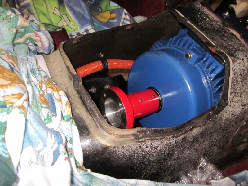
William got this great shot from looking under the diff forward to the motor. I really have pressure cleaned the underside but I think it needs scrubbing as well - there is no loose dirt left.

The conduit going past the motor rear mounts. This way it won't get in the way if I have to remove the motor.
He got a better picture of the conduit going over the axle too.

Here is how the conduit gets into the boot. This is under the boot mounted contactor/fuse box on the left side of the car. It's all siliconed up now. You can just make out the conduit bracket on top of the axle that is mounted to the axle limiting rubber buffer. There has been no need to drill holes in any chassis rails.

Finally, a picture of the traction cable wiring prior to putting the top battery tray and controller tray in. The orange conduit running low down alongside the motor is the front-to-rear conduit shown a few pictures above. More garbage ties....


No comments:
Post a Comment