This blog documents the restoration, and conversion, of a 1965 Humber (Singer) Vogue to a fully electric vehicle. The Vogue will be powered by an 11kW(modified), 3 phase industrial AC motor, controlled by an industry standard Variable Speed Drive (VSD) or Inverter. To be able to produce the 400 volts phase to phase the VSD will need about 600 VDC of batteries. A big thanks to the contributors on the AEVA forum: http://forums.aeva.asn.au/forums/

Thursday, September 26, 2013

EV work sidetracked by Home Renovations

I'm back driving the Vogue daily (since Monday) after my slight scare with the battery pack (which is working fine now).
I'm trying to track down another BMS for the battery packs as I do not have a spare. If a BMS dies for some reason it will put me off the road. The problem is that the BMS in my packs (WL086-05) is not available any more. The closest thing to them is a 16 cell BMS from EV-Power at 120mm x 90mm and I only have about 110mm x 90mm room in the pack.
At least I know where to get one now and there is a chance I can slice 10mm off it in the power FET area. I hope I never have to find out but it's best to plan.

Anyway - house renovations.
In the last few weeks I have demolished a built-in wardrobe pair in our main bedroom. By built-in I mean it. It was part of the original house framing even to the point where two of the ceiling bearers didn't make it to a load supporting wall instead being secured to the wardrobe framing (I extended them). The reason for it's removal was that in a house with 2.7M ceilings, the wardrobe was only 2M high. The remaining 700mm above the pair of wardrobes (on a 4M wide wall) was roof space. There were two wardrobes, each 1.5M wide with a dressing table that we didn't use in the middle. Add to that - they were only 450mm deep - most are at least 550mm deep. A real waste of space.

I also had to patch the floor. Fortunately the tongue and groove boards that formed a shelf in the wardrobe were actually floorboards (the white ones in the picture).


So I removed the whole lot and re-plasterboarded the area.

Since taking this picture I have done the first "mud" and tape coat.

The new wardrobe get installed in early October and they will trim the cornice and skirting boards to the correct dimensions to butt against it.

So I have two more coats of "mud" then we have to get the area painted.
Plus other stuff...


Demolition in progress - a tad blurry - sorry.

Thursday, September 19, 2013

Pack #5 Fixed and ready for Car.

I temporarily plugged the relevant parts of the BMS into the pack last night and charged it while the pack was still open and I could measure the cell voltages.
The cells were so perfectly balanced that the charger current died off at 59VDC with around 3.68V across each cell pair - so no balancing required.
I did  a quick test of the BMS monitoring (my opto-coupler mods) and it checked out.
The BMS is fine - no damage.
After now leaving the pack open for 24 hours or more to thoroughly dry out, I re-assembled the pack last night but it was too wet and rainy to bother putting it back in the car.

I'll put it back in tonight or tomorrow morning.

Astute readers my notice that this pack is identified as Pack #10. That's because, way back when I had problems with controller switching coupling from the motor leads into pack #10 in the engine bay, I swapped packs #5 and #10 - just in case.
It remains an annoying facit of always having to note which pack #5 or #10 I am dealing with in my pack notes.


If I ever have to pull the faraday cage off Pack #5 (engine bay - see), I'll shield Pack #10 (the one shown above) more elegantly and swap the packs back to their rightful positions.

Wednesday, September 18, 2013

Pack problem caused by Water

As soon as I got home from work last night I yanked Pack #5 from the boot (trunk), took it inside and pulled it apart. There was a little bit of water on it and a few drops on the tray but I kind of ignored them until I got the pack apart - a little water dribbled out but I still wasn't sure that it didn't get on the pack when I was removing it (boot lid was very wet). I checked all cells and all measured 3.27V per cell - no variation. So the cells were OK. I proceeded to remove the bottom of the pack enclosure - now it was obvious.

Most of the bottom cover was covered in a thin film of water with a patch about the size of a matchbox (50mm x 40mm) that had green tinged foam/slime around it - that's where the BMS's daughter board was sitting in the pool of water!
BMS daugher board circled in red. (Daughter board appears to be so they can use the same BMS for 12 or 16 cells systems. They add four more cell handlers on the little board.)

Unfortunately my sense of WRONGness was so great I instantly wiped it all up - then remembered that I should have taken a picture - oh well.

I removed the BMS board and cleaned it with genclean (PCB cleaning stuff) then resoldered any suspect looking pins (a couple of Molex pins looked like they had corroded slightly), then gave the board a coat of clear laquer.


OK - so where did the water come from.
Some while back I crowed about how the Vogue was fine charging in the rain because the charger inlet (located IMMEDIATELY above this water soaked pack) had a "moat" that went to a drain hose. Well the 48 year old drain hose had cracked even more than when I re-installed it and was leaking every time I charged in the rain. Also, any water that got under the unsealed cover while driving went down the drain hole/hose.

The charger inlet, "moat" and drain hole in question.

I cut the bad end off the hose and ran the hose in a straighter line (no fuel tank to go around).
View inside the boot.


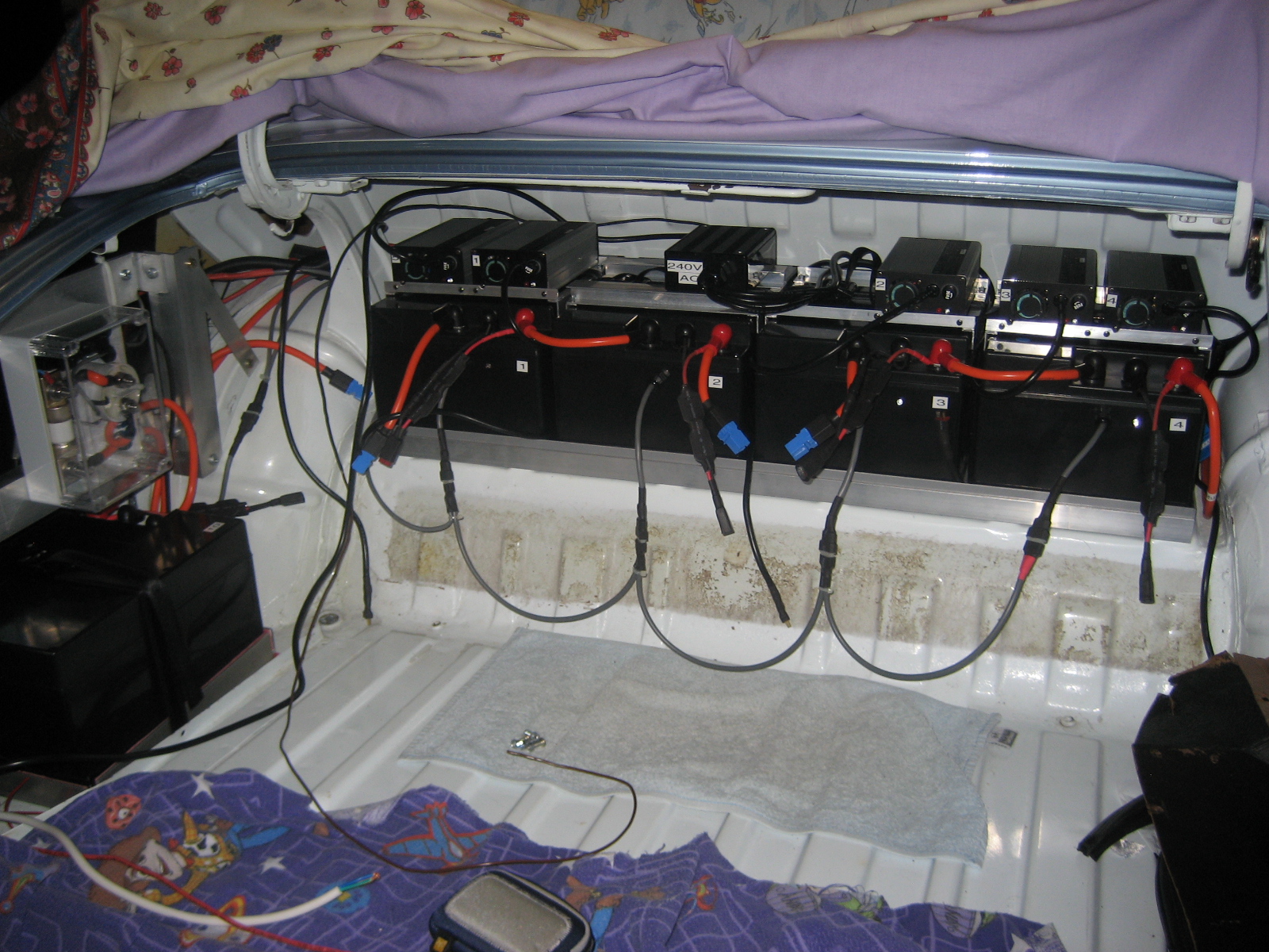
This old picture shows where Pack #5 is mounted with respect to the charger inlet. It's the one sitting alone on the left under the contactor/fuse box.

I haven't tested the BMS board yet to see if it still works - fingers crossed.
I'll try to get the pack back together tonight - it's still in the state of the first picture in this post.

When I re-install the pack (assuming the BMS is OK) I will put a temporary cover over the pack and check it regularly for a while.
I am still amazed that the water had got into the pack enclosure so easily. The three packs under the front of the car (engine bay) have been sealed with waterproof gaffa tape but now I wonder about them as well. At least their orientation would not have the BMS board at the bottom of the pack like this one.

...and yes, I am very embarrassed.

Tuesday, September 17, 2013

Battery Pack Problem

I didn't drive the Vogue today. When I started it the battery monitoring system instantly sounded an alarm. A quick check showed Pack #5 in the boot (trunk) had it's indicator light off. I re-connected the charging lead but it's internal BMS switched off the charger path straight away. I took my daughter's car to work.
I'll check it out when I get home.
I have a sneaky suspicioun that I just had my first cell failure in active use (later edit - wrong - they are fine). Unfortunately my packs will tend to kill two cells at a time due the the two-parallel nature of the system.
At may be that my 65km on Friday night has pushed some week cells into failure (nope - see next post). I did have two cells fail while in storage - a couple of years ago now (and to date they are the ONLY two).
I'll post the results...

Tuesday, September 10, 2013

Longish trip and Wombats

Last Saturday I had to drive 27km down to Chelsea and back and it was interesting. I got to my destination with 54km remaining range which was fine (total 81km). On the way home the total reduced to around 77km. Each time I stopped from 70km/h I gained around 1.5km then when I accelerated back up to 70km/h I lost around 2km.

The interesting bit was when someone in front of me had a brain freeze and caused me to do a faster stop than I would have liked - so I had to use mechanical brakes. I lost just under 2km range when I took off again having not got it back from regen first. So from that point on the trip plus remaining range at at 75km.
All this is measured to 80% DOD on a 12kW/h pack. The more you start/stop - the more regen. is important. I can't imagine it being anywhere near as much fun driving an EV with no regenerative braking - I rely on it.

On other matters. We had four Wombats visit work today. One of our engineers and his wife look after wildlife and they currently have a plethora of Wombats.


Jacob had a hold of a naughty Wombat.


When Wei tried to have a hold he just wanted to get away. A VERY naughty Wombat.

Monday, September 2, 2013

Suddently the sun broke through.....

Even Gaia likes EVs.
This was the view as I left work and walked up to the eVogue on Friday late-afternoon.

Thursday, August 29, 2013

2000 Kilometers as an EV

The Vogue Odometer passed 2000km on the weekend.
This picture was taken later in the week.

Tuesday, August 20, 2013

Rear Windscreen Sealed - back driving the Vogue

I finally got to the Vogue on Sunday afternoon and sealed up the rear windscreen glass-to-rubber interface. It took a whole 15 minutes. I drove the Super Snipe to work Monday (yesterday) as I don't like to put it away after only running it for a few minutes (rust out exhaust) - so I swapped cars as soon as I got home. With my wife's car and daughters car - and my two, it's not that easy to change over the Vogue and Super Snipe to/from the garage. Most times I have to move three cars (anyone seen "The Castle"?). I'm back in the Vogue today. It will be raining off and on for most of this week so I'll keep an eye on the rear windscreen.

The accelerometer arrived (eBay) yesterday and I had a quick play - it looks like it will do quite nicely. I had to decide whether to keep the Vogue in the garage for another week so I could do the axle stand thing or drive it this week. Based on my poor track record last week (nothing but the rear windscreen done) I decided to drive it. I have to make up a little bit of electronics to trigger the LED strobe from the accelerometer anyway so we'll see how I go with that!

Friday, August 9, 2013

Vogue off the road for a few days

I'll be driving a dinosaur to work today. It doesn't slow down all by itself - I have to press the brake pedal. Then the engine keeps running even though I have stopped. Going down a big hill, instead of adding to my range, It drops brake pad powder on the road and heats up the brake disks and drums. Acceleration is weird - it loses torque in stages (gear changes). All truly archaic.
Yes, I'll drive the Super Snipe to work today.
Why? Do I have more distance to travel than the EV can manage today? Is there an electrical malfunction with the Vogue?

Nope. The rear window leaked with the massive rain we have had over a past week. I noticed it yesterday in the work car park - the rear window was foggy on the left hand side so I investigated.

When we installed all the glass in the Vogue I took counsel that having a velour headliner might be a problem if any water got under the rubber seals - so I was very careful to use Butyl Mastic between the seals and the bodywork. The seal to glass interface - not so careful. I did the corners, but not across the bottom

The front is fine but the rear window is leaking where the glass goes into the rubber seal. It's no problem to fix but I have to dry it out and clean it before sealing it with Mastic - so it's out of the rain in the garage today.

I have circled in red where the water leaked in. It was quite easy to see water seeping over the top of the rubber seal on the inside. I'll remove the rear parcel shelf mat and board and dry them out as well. 
This will also give me a chance to work on the Vogue at night next week. I might even get the heater back in. If my accelerometer arrives early next week I'l try to get my home-balancing system working as well.

I also have a new configuration to put in the controller that is different enough that I should put the car on stands to try it. The new config has more ramp elements to make regen cut-off at 1km/h gentle and some other refinements.

Tuesday, August 6, 2013

First step toward building an on-vehicle Tailshaft Balancer

I alluded to this in my previous post and I realised that I should elaborate on my intentions regards tailshaft balancing.
The final straw of getting help with the tailshaft issue came after I rang a Ford service manager and enquired into on-vehicle tailshaft balancing. I had read on a couple of Ford forums that some Fords required the final tailshaft balance to be done on the vehicle.
The service manager was very helpful and pointed out that the balance is done in conjuction with a diagnostic tool that plugs into the car's ECU (that's not what I thought but he was adamant that it only worked with Fords). No hope there.

So, I have bought one of these off eBay. It's a three axis acceleometer with analogue outputs.


It claims to be highly sensitive. (So is our dog [the rag stealer] but she hasn't helped. She's only allowed on the bed if she has just been washed and someone is sick - special times).

I'll be making up some simple electronics to detect one of the output signals and flash a high-intensity LED at some repeatable point. It then should be a matter of:
  1. Secure the accelerometer board to the motor frame.
  2. Shine the LED at the tailshaft
  3. Run the car on axle stands
Of course nothing is ever simple so I'll start by looking at the signals on a CRO and seeing what I've got.

I'll use hose clamps initially and place one on the tailshaft to deliberately mis-balance it so I can calibrate it all.

Then the whole shebang should tell me where to place the balance weight. From there it's should be just a matter of varying the weight to minimise the vibration.

I make a big effort to blog this as I go, success or not!

On other matters - we had a really nice storm last night and the Vogue was the last car home so had to be charged in the pouring rain. No problems. The plug was dry when I unplugged the EV "special" extension cord. In fact I was more concerned about leaks in my new rubber seals (windows, doors) throughout the car - also no problems (hmmm - see later posts).

Monday, August 5, 2013

This week's economy

Figures for week ending 2nd August 2013
Monday: 8.34 AH for 39.42 km => 127 Wh/km
Tuesday: 6.36 AH for 30.84 km => 124 Wh/km
Wednesday: 8.94 AH for 40.4 km => 133 Wh/km
Thursday: 8.37 AH for 36.38 km => 138 Wh/km
Friday: 9.24 AH for 42.84 km => 129 Wh/km

All battery to wheel.
I increased the available regen torque to 45% of forward torque this weekend.
I doubt it will make much difference but may slightly increase my overall trip speed as I can slow down faster.
We'll see.
Still waiting on my eBay accelerometer so I can do my own on-vehicle tailshaft balance.

Sunday, July 28, 2013

Only One Fuseholder Remains - Economy Figures

I didn't post it at the time, but last Tuesday night I removed three of the last four inline charger fuseholders. I have one left and it's only there because I ran out of 4mm black heatshrink and it was the only one that looked to be in perfect condition. I'll do it as soon as the heatshrink (from eBay) arrives. With the fuseholders gone the Vogue was completely trouble free for the commutes last week.

Figures for week ending 26th July 2013
Monday: 8.84 AH for 39.2 km => 135 Wh/km
Tuesday: 6.68 AH for 31.9 km => 126 Wh/km
Wednesday: 7.20 AH for 33.6 km => 129 Wh/km
Thursday: 9.81 AH for 43.4 km => 136 Wh/km
Friday: 9.38 AH for 42.9 km => 131 Wh/km

(All battery to wheel)

As a curiosity, I usually make it to work at about 3 AH consumed - that's around 1800 Wh making the economy about 120 Wh/km (my record so far is 2.8 AH). The trip home is a lot worse and I have generally racked up over 6.6 AH by the time the round trip is completed. The difference in altitude is about 20 meters so doesn't explain it - but driving style does. Going to work I am generally not hassled by any other drivers so I can accelerate slowly and slow down at my leisure taking full advantage of regen braking. Driving home is a relentless wrestle with other road users to use as much regen as possible but not get in their way. The nett result is that driving home is less efficient. Accelerating up hills costs a heap of capacity.

My observation is that not many drivers are in a hurry to get to work, but most road users are in a hurry to get home.

I could improve this situation with more regen. At the moment it peaks around 25 Amps (battery) which is 1.25C. Headway (battery manufacturer) recommend a continuous charge current of of 1C (20A) and maximum continuous charge of 2C (40A). Perhaps I'm being too conservative. I really haven't had much time to mess around with configuration in the past few weeks.

Tuesday, July 23, 2013

Banana shaped fuseholders

I mentioned a post or so ago that some of the inline charger fuseholders have melted out of shape a fair bit.
This one is on Pack #5 in the boot. It hasn't failed yet - amazing! (The large flat heatshrink bit houses the two 3A heatsunk diodes that isolate the charger from the pack and the lower black wire and clump are the inline fuseholder.)

I only have three of these inline fuseholder left in the car - out of 12.

Pack #9 gave a low voltage alert about 800 Meters from home last night. I gently eased the car home and sure enough, the fuseholder had failed and Pack #9 hadn't charged much the night before.

It was 44.3 V unloaded and charged up fine with a clip-lead replacing the fuseholder.


Monday, July 22, 2013

Economy figures for last week

It's actually been interesting driving the car in these colder months without a heater. The economy is slightly worse than when it's warmer and we can't blame the heater!

Figures for week ending 19th July 2013
Monday: 5.89 AH for 24.8 km => 142.5 Wh/km
Tuesday: 6.78 Ah for 30.6 km => 133 Wh/km
Wednesday: 10.34 AH for 44 km => 141 Wh/km
Thursday: 7.62 AH for 34.25 km => 133.4 Wh/km
Friday: 7.61 AH for 31.7 km => 144 Wh/km
*Friday after at-work charge: 12.6 AH for 50.67 km => 149 Wh/km

As usual all figures are battery to wheel.
I didn't really have to charge at work on Fiday but I had a Chiropractor appointment in the morning then I chose to do the running around on Friday night in the Vogue. It's two trips to Doncaster and back and the big hill takes it's toll. So much for "the most I have driven in the last few years during weekday is 58 km".

Last "under the car" fuseholder bypassed

I didn't get to play around with the tailshaft this weekend but I did manage to crawl around under a slightly raised car and bypass the last of the hard-to-get-at fuseholders (in series with chargers). This was the one attached to pack #10 that I mentioned in the previous post. There are now only six of the unreliable fuseholders left and none of them are hard to get at.

One of the fuseholders in the boot still works but the heat has bent it like a banana.

Wednesday, July 17, 2013

Three more fuseholders bypassed

I spent about an hour and a half under the front of the car last night squeezing my hands up beside the inner front guard to cut out two of the offending fuseholders (packs #11 and #12), substitute a length of wire, and heatshrink the whole lot. The time was mainly spent trying to line up two pieces of wire (several times) with only one hand (tried many clips etc.) and solder with the other - while scrunched up in strange positions.

I also did the same treatment to pack #8 in the Engine Bay.
Pack #10 inline charger fuseholder is also about to fail. It's the hardest pack to get at without removing the top battery tray so I'm hoping it will hold on a week or so as I will be removing that tray to change the heater blower soon. It's marginal - if you rattle the charger wire while charging, the charger cuts back to balance mode - sigh.

So, fully charged again,  Il drove the Vogue to work today.

Vibration wise. I have now driven the car for a couple of days and the vibration is only a little bit better than it was with the M8 bolts holding the front flange in (allowing the spigot to be centered). While 90 km/h is possible, it feels the the motor bearings won't survive long. It's going to be a wet, cold weekend so I hope that I both get the time, and the enthusiasm to brave the cold and check it out further. I have my hose-clamps ready.

Tuesday, July 16, 2013

Timer waits for no-one - Neither do inline fuses!

I didn't drive the Vogue today - there were too many obstacles.
Firstly, last night I plugged into my wall timer and checked that is was set to auto - only to find that it had stopped entirely. The timer is a Chinese copy of the TP8A16, 16A 240 VAC timer.

It was designed to come apart, so come apart it did!
The 1.2V, 80mA/h NiMh button battery had EXPLODED.

I removed the cell and checked out the rest of the board - it appeared fine after a little cleanup.
A quick reverse engineer and I discovered that they use the battery as a 1.4 volt regulator. Without the battery there is about 6 volts at that point. The electronics doesn't like that so it didn't work. When I turned off the 240VAC, it worked for a few seconds as the voltage went down through the acceptable region. So the electonics was probably OK (amazing).

I removed the exploded cell and substituted two diodes in series where the battery used to be. It all worked fine. It only lasted about 5 seconds after mains disconnect but that would do for the night.

At least they used a 16 A relay.

I went out to the car at around 6:45AM this morning to check all was well (timer was set to start at 5AM and finish at 8AM) - but all was not well. I charge at 3 Amps and needed 6.6AH - so a bit over 2 hours required.

Battery pack #12 was indicating finished charging - all the rest were still charging as they should have been.
I checked pack #12 and it certainly wasn't fully charged - another inline fuseholder! I should have had them all changed out by now - oh well. previous fuseholder failure

Pack #12 is under the controller tray and hard to get at so I'll take my daughter's car as she is not due home until Thursday and I have to give it a full tank and wash it anyway.
That way the Vogue is also in the carport for some wiring surgery tonight. I'll try to bypass all three fuseholders under the engine bay without removing the controller tray. I'll see how I go...

Monday, July 15, 2013

Tailshaft on again

Well the tailshaft is back in the car.
The balancing folk identified that the spigot on the front flange of the tailshaft and the "cup" in the coupler did not perfectly match. To quote Jeff, "any movement is too much". They changed the flange on the front of the tailshaft then balanced the whole lot together.
(I suspect that the flange was imperial and someone machined the coupler to a metric size believing that the flange was metric.)
The front flange holes now comfortably fit the M10 bolts (butchering gone).

It's a lot bit better - but it's still not perfect. At 90 km/h on the tollway it wasn't scary - but it wasn't comfortable either - still a lot of tailshaft speed vibration.

I didn't put it on stands to test it as I had very little time, but I hope to do an axle stand test maybe be next weekend.
My plans is to:
1. Record the vibration audio again just because I am not sure that it's vibrating at tailshaft speed - it feels double that.
2. Try my SS hoseclamp at 45deg increments.
3. Try dampening out the front motor cradle (with my hands) and see how much that is contributing.

I drove to work with about 4.5km of my 15km drive on the tollway this morning at around 90 to 95km/h (traffic speed in left lane) and the Vogue used almost the identical amount of power as when I drive to work via slow backroads. I backed into my parking spot with a reading of 3.14 AH. That's about 125 Wh/km battery to wheel. Wind was practically non-existant - the BOM site also showed almost no doppler wind reading. Current consumption at speed was quite modest. So the Vogue CD isn't awful at all.

Saturday, June 29, 2013

Another place - another blog - Refugees

I don't normally introduce anything to this blog that isn't related to electric cars but sometimes there are exceptions. My daughter, Tammy, is in Geneva at the moment doing a unit at the Murdoch University on International Refugee law. This post is a must read for Australians - in my opinion.
http://tammyingeneva.blogspot.com.au/2013/06/refugee-rants-and-eating-badly.html

A link to her whole blog:
http://tammyingeneva.blogspot.com.au/

I'm still awaiting my tailshaft's return.

Wednesday, June 26, 2013

Tailshaft and Coupler at the Balancer

The tailshaft (driveshaft) and motor coupler are out of the car again and at the balancers.
They are going to thoroughly check out the mating between the two and balance them as a set.

Tuesday, June 25, 2013

More Heater Woes

I have good news and bad news.

Good news #1 is that I know that I can drive for at least 25 minutes withOUT the DC-DCs running into my 9AH 12V battery. In the daytime anyway.

Good new #2 is that I now also know that the NS syle BS88 16A offset blade industrial fuses that feed +300V and -300V into the Heater and DC-DC, simultaneuously blow and safely disconnect the 600VDC from both the afore-mentioned. When replaced with 20A (that's all I had) they safely blew again. (I crushed one in a vise after it blew and the sand had nicely fused to break the Arc).

The bad news.
My heater stopped again rather dramatically. It had worked for about 3 days then one morning last week - no heat. After about 12 minutes of driving I decided that the 12V turn indicators were a fraction slow and pulled over to check the 12V battery - 12.0 volts - not good. There was no power to the DC-DCs. Neither +300V or -300V - which surprised me.

So I went back home because I wasn't carrying spares or even a screwdriver.

I disconnected the heater (funny that), replaced the fuses and DC-DC was back again. 13.6V on 12V battery.

While live (car on) I reconnected the heater -300V all OK, then +300V SPLAT - BUUMPH! Both 20A fuses blew at once.

So I have the heater controller out again. The IGBT AND the Fast recovery diode across the Ceramic element have shorted. It also blew a bit of track off my PCB.

Is PWM controlling a ceramic heater element that hard?
The bottom of my control board. I have circled the missing bit of track. The missing track used to connect the fast recovery diode across the heater element.
After a heap of discussion on the AEVA forums we have finally concluded that ceramic heater elements have very high capacitance. That's why they are not suited to PWM control. The power IGBT is switching into something close to a short circuit at normal switching rates.

In other news, somewhere last week the Vogue passed 1100kM as an electric vehicle.
I'm not driving it this week (or late last week) due to 1 degree C temperatures on Melbourne mornings.

Friday, June 7, 2013

Checking it's been Charged

I have a 15A timer on the wall of the carport to set my charge time and I don't use any kind of watt/hour meter to measure charge - and the car itself can't measure charge. So my primary method of checking if the Vogue charged during th night is the Energy Easy website which links to our electricity Smartmeter.

Here is what I see when I log in each morning.
 The Vogue starts charging at 2AM currently and is generally finished by about 4:30AM. The peak at 6:30AM is our bathroom towel rail turning on. The website is very useful as one morning a few weeks ago I logged on to find no peak at 2AM. The previous night I had checked all chargers by switching the timer to On, then pressed the button again to switch to Auto On and instead switched it to Off. Now I know to press it twice and also check the display.

No Problem Charging in the Rain

The Vogue was the last of three cars into our single lane driveway last night. I took the opportunity to measure up the shortest reasonable length of extension cord that would make it from the mains timer in the carport to the car and cut down my 25 meter Bunnings cord to 12 meters. I haven't blogged it yet, but the socket end now has a custom "shroud" on it that covers the Vogue fuel inlet nicely. Water is directed via a lttle moat through a tube to underneath the car. That's the original system. Anyway, it charged with no problem and this morning when I unplugged the cord from the car the pug was dry. The hinged fuel cover was another matter but a quick dry with a towel helped before closing it - I'll make up a plastic "sock" of some sort for that - no biggy.

As I left it last night.

I added this next photo to this post on the 29th July. The white part of the socket is a $2.50 plumbing fitting cut to size and glued on so that is extends about 3mm past the end of the extension cord's socket. Since the Vogue's plug is elevated above the "moat" by the same amount, it forms a splashproof connection. You can see the drain hole which goes via a plastic hose in the boot (the original) down through to under the car. I have now charged several time in pouring rain with no water at all getting under the socket.

That's not my 150K Ohm resistor - it's in the original sealed socket! The socket has a pathetic little red LED that is barely visible when the power is on.

Thursday, June 6, 2013

A Tail of Two Flanges - The Tailshaft saga

Reading back over the blog when I first installed the tail shaft I kind of skipped over some of the messing around I had to do to get it fitted.
One of the reasons I didn't blog all of it was that it seemed like a criticism of the guys that made the coupler and tailshaft and the problems were sorted out pretty quickly - but maybe they weren't after all.

Here is the whole story.
The first ever time I installed the tailshaft, it took me a longer time than I would have thought possible to realise that the four bolts that hold the front tailshaft flange to the motor coupler didn't actually line up. The holes in the motor coupler, while being the correct Pitch Circle Diameter (PCD), were arranged equidistantly around the circle. The universal joint flange on the front of the tailshaft was arranged as a rectangle. This is pretty standard for universal joint (UJ) flanges - at least with cars that I have played with.

This picture isn't of mine but shows what I mean. The two holes on the right are closer than the two holes across the top.


That being the case, the first drive of the Vogue had the front of the tailshaft being held to the coupler with two M8 bolts 180 degrees from each other as all four bolts could not be fitted.

Obviously I wasn't going to leave it that way, so before the second drive I removed the coupler and tailshaft and took them back to the guys that made them and they added some holes and tapped them out to M10. (The original M8 tapped holes were left alone).
When I got it all back and managed to find some fine thread M10 bolts of the correct length, I took another huge period of time under the car before I decoded that there was no way I could get these standard hex bolts in past the universal joint ears (the bits jutting out that hold the cups). So a day or two later I bought some M10 Allen head machine screws.

Again I messed around for an hour or so trying to get these in with no success. They fitted through the tailshaft (UJ) front flange OK but would not all thread into the motor coupler when I offered it up. At some point I realised that the tailshaft flange holes were imperial 3/8 inch - that's 9.525mm.
So I pulled the tailshaft out completely, held the tailshaft as best I could in my workmate, and hand drilled the holes out to 10mm - the biggest drill I had. I cleaned up the facing side of the flange with a 1/2 inch drill bit and ensured there were no burrs.

Once the holes were drilled out, I could almost get all the bolts in by hand. Importantly I could now place the tailshaft flange on the coupler flange, mate the spigots up (the 60mm diameter sections used to correctly locate the flanges) and insert and tighten the bolts up. There was always one or two bolts that I had to pull in with the Allen key the last 6mm or so but it all looked correct.

I explained this to the guys that made ther tailshaft and coupler but they weren't too concerned and have had the tailshaft back twice since then.

So now we are up to this week.
When I picked up the tailshaft on Monday night, it was explained that the balance was fine and they hadn't changed much. It fitted it Tuesday night and it behaved pretty much the same way as before. However, this time I had arranged a system were I could control the motor speed while lying under the car so could have a "play" without having to ask someone else for help controlling the speed. What I found was, even though earlier tests showed the front of the tailshaft rotating without excessive runout, that was not the case on the slip yoke. The UJ flange rotated true but the inner part of the slip yoke did not.
I whittled a chunk of wood and tried moving the UJ centers in their housings (in the direction that would remove the runout) - no give at all (they were properly installed and very good).

For some reason I decided to remove the four M10 bolts and track down the two M8 bolts and washers that I had used on the first drive.
Once I had the tailshaft bolted to the coupler with only two M8 bolts, there was an immediate and substantial improvement. I made a further slight improvement by loosening the bolts and using the tiny bit of play in the spigot to move the mating flanges in a direction that would help.

That's how I drove it today - a lot better. Not perfect yet, but better.

It appears that there is a concentricity problem in the front slip-yoke and UJ combination at the front.
If the tailshaft is being held by the front flange during balancing I would think it would be balanced out.
So we know what it is, the front end of the tailshaft involving the slip-yolk and universal joint - now to fix it completely.

A note here. I measured runout months ago and concluded that the tailshaft was fine. The closest I can normally get to the front of the tailshaft is about 300mm from the front, and it's a lot better at that point. I've got a lot braver with rotating machinery (while still being careful) over the time. A whole lot of factors have conspired to create this problem and make it hard to track down. My inexperience hasn't helped.

Edit: Some changes made for clarity thanks to comments from AEVA forum member weber.

Tuesday, June 4, 2013

The Tailshaft returns

It's back. I'll try to get it on tonight. I need the car mobile for Thursday.

I picked it up yesterday afternoon but there was no great hurry to re-fit it as Jeff from Precision Balancing indicated that there was no significant change (I also cooked dinner last night amongst other things so time ran short). We may have come up with a way to do an on-site balance of the whole drive train while the car is on stands. I'll post when I have more info.

Tuesday, May 28, 2013

The Tailshaft's away - with the Heater Blower I'll play

The tailshaft is out of the Vogue again and with Precision Balancing. The short story is that I have eliminated everything except the tailshaft. I suspect the slip-yoke and front Universal Joint. I'm hoping they can balance the whole lot as a unit.

While I await the return of the tailshaft, I have turned my attention to a noisy heater fan/blower. When I painted the blower and housing I actually didn't quite know how the get it apart fully - I also didn't know if I had a viable spare so I wasn't too choosy. Having found another one under the house, I totally stripped it apart, de-rusted where required, primed and painted it. The bushes in the motor in this one appear to be quite good - not worn and rumbly like the one in the car presently.

I have re-attached the motor in this picture. It's ready to go together again and have the foam fitted to seal the inlet and outlet gaps.

Monday, May 20, 2013

Wedges Installed - Problem persists

I finished installing the two degree wedges on both sides of the car on Sunday afternoon.

This is the front - about 4 to 5mm lift.

This is the rear of the axle perch.

The underside - just 'cause I took the picture.
The differential flange and the motor coupling flange are now within about 0.3 of a degree of each other.

....and the result. Absolutely no change at all!

We even locked the motor speed to 60 km/h to remove any doubt about speed variation and placed a big block of wood under the rear of the motor mount and jacked the car up about 15mm - no change.

I repeated a previous test and jacked under the middle of the motor cradle (the fan end of the motor) - no change in vibration. This stumps me. How can it be that taking so much load on the jack doesn't at least dampen the vibration?

I don't believe I have ever in my life put more effort into a problem with so little return.

So I am faced with a choice now of whether to give up on universal joints and have the tailshaft remade with CVs or persists in trying to find the reason for this vibration. Going the CV route doesn't automatically gaurantee a cure.

Suggestions from mechanically minded folk are very welcome but if you want to comment, please could you read the posts on vibration so we don't revisit older discussions too much (that isn't to say I haven't missed something).

I'm currently trying to ascertain what sized tube wall was used in the new tailshaft.

Friday, May 17, 2013

Ready to Re-assemble Driver Side Spring Mounts

I had wire brushed all the axle/spring mounting hardware a couple of days ago and applied rust converter. I cleaned off the rust converter residue and primed the bits last night. I gave them a coat of gloss black this morning. I can't paint inside the house or in the garage due to overspray, so It's a process of warming up bits (and spray cans) inside, painting the bits outside, then bringing them back in. I guess it doesn't matter much if glossy black bits under the car are slightly dull - but I'd know!

If my hands can keep from seizing up with the cold I'll re-assemble the right hand side tonight.

Wednesday, May 15, 2013

Changing the Differential Pinion Angle

My spring wedges (sounds like a potato treat with greens), arrived yesterday so last night I set about separating the axle from the leaf spring on one side of the car. I jacked up the car under the diff housing then placed the two rear body jacking points on axle stands. Then I lowered the jack until it was only just supporting the weight of the rear diff/axle.
The U clamps came off pretty easily (with the aid of some CRC56).Once the U clamps were off, I jacked up the axle slightly to removed the top rubber mount.

You can see the leaf spring centre pin that locates the spring on the rubber mounts (next photo).

A slightly blurry picture of the U clamps, upper and lower spring mounts and shiny new two degree wedge.
 

View from the rear of the car.

The spring wedge in the upper insulator/mount. The upper rubber insulators are not in very good condition but I tried unsuccessfully this morning to get new ones. I'll put these back in and keep trying to find a replacement now that I know how easy it is to "drop' the rear axle. I think I'll make a thin wedge to go in that gap in the wedge as well.

The left hand side - still intact. I'm doing one side at a time. That way the "other" side holds everything in place and I don't have to worry that the whole axle will fall out on the floor - tearing the brake lines in the process. The oil stains are an old testimony to (now-replaced) leaking rear oil seals.
I'd love to pull the springs out and clean the whole lot up but I want the Vogue back on the road ASAP. Maybe next year...

A couple of paragraphs from the workshop manual. It's interesting that Mr Rootes sometimes fitted wedges. No, I didn't find any.


Friday, May 10, 2013

Economy Figures for Week-before-last

I forgot to post these. I didn't drive the Vogue last week but the week before with the controller switching at 8kHz and me driving the lowest speed roads I could find for my commute returned some excellent power economy.

Economy figures for the week ending 3rd May 2013:
Monday 9.46 AH for 43.4 km => 131 Wh/km
Tuesday 6.33 AH for 30.77 km => 124 Wh/km
Wednesday 6.55 AH for 30.8 km => 128 Wh/km
Thursday 10.28 AH for 44.9 km =>  138 Wh/km
Friday 6.77 AH for 32.4 km =>  125 Wh/km

As always, all battery to wheel.

Heater Tested and Ready for Re-Installation

Yesterday evening I tested the heater to my satisfaction. I arranged for a temporary control potentiometer and 12 VDC power source for the control board, strapped a blower (funnily enough, the original blower that came out of the donor ceramic heater) to the side of the heater box, placed the whole lot alongside the car and plugged it into the 600 VDC connectors. I "started" the car (engaged traction contactors) and ran the heater for 5 to 7 minutes through a range of heat settings. I then ran it for about 5 minutes at 1.0 Amps - that way I would see immediately if the IGBT ran into trouble as the current would rise to 2 Amps - it didn't.

Another technobabble alert
Just a side note here. During the 12 VDC testing a few days ago, I noted a 1 MHz pulse train at the start of each switch-on pulse - it ran for about 16uS which is significant at the 64uS PWM rate I was running (now 9mS).
Here is a picture of the rubbish at the switch on point measured at the gate drive output. This is with my 9mS PWM rate (110Hz).

I tracked it down to excessively long clip leads going around my test bench causing the switch pulses to get back into the control analogue input. I largely suppressed the effect with a 10nF capacitor across the TL494 voltage op-amp output to -ve input; but it may have been the cause of the IGBT failure. I added the cap. before I realised that it was the leads causing it - but left it in anyway. The input control wires are shielded cable so maybe it wasn't the cause of failure - anyway - worth mentioning.
End technobabble (largely)

Once the test was done I shut it all down, quickly unplugged the 600 VDC connections, lifted the lid (not screwed down yet) and tested the IGBT and various other components for temperature - the finger test. The IGBT heatsink was cool and the only hot components were the two current surge limiters (they are supposed to run hot) - and of course the ceramic element which had already cooled so it was only warm to the touch.

That done I took the box inside and stuck everything that might move firmly in place with the red RTV silicone I've come to know and love.


The heater box is ready to re-install.

Tuesday, May 7, 2013

Heater Repairs

While I am waiting for my axle/spring wedges to turn up I turned my attention to my non-working heater. I removed the entire cabin unit and extracted the recalcitrant control board. Sure enough the IGBT was a short circuit.

Prior to removing the control board (in the litle grey case). The arrow points at my off-board snubber capacitor.


WARNING - Technobabble alert
I replaced the IGBT, changed the PWM switching frequency from 16 kHz to 110 Hz, placed a 20V Zener accross the IGBT Gate to Emitter and finally moved the 1uF 1200 VDC snubber capacitor to directly onto the PCB. I tested the whole shebang at 12 VDC with a 24W light globe as the load.

All fixed. The snubber is now a power bulge in the gray case (red arrow). I'll RTV silicone it all up when I have tested it with 600 VDC. Note the extra heatshrink where the wires emerge from the control box and generally tidier wiring. The heater wasn't that easy to get out so I don't want to do it again soon.


Friday, May 3, 2013

Driving my thougths to Vibration

While driving the Vogue every day this week, I seldom go for more than a minute without thinkout about my driveline vibration issue. For the time being, I have found ways to and from work that allows me to keep the speed below 55 km/h except for an approximately one kimometer stretch. I can pull in and let traffic go past then keep speed down here as well - usually. Curiously this makes my 25-30 minute commute about 30-35 minutes. Not a substantial difference but no-one likes to travel slowly when they can legally go faster - and it's frustrating because the Vogue's power curve makes it way more fun at higher speeds.

Anyway my thoughts during this drive waver around in the following direction.
Back when I orginally identified that I had a driveline vibration, my first impulse (after tailshaft
balance) was to think that it was caused by the differntial pinion angle. Essentially a Universal jointed
tailshaft will vibrate a lot if the flanges on either end of the drive system are not at the same angle
with respect to the line of the driveshaft.

We thought we had dispelled this theory by temporarily altering the pinion angle using axle stands and a jack, and moved on to removing the motor, dismantling it and having the rotor balanced.
All to no avail - apparently...

Well, looking back I note in the blog (my reference source for all thing EVogue), that at the time
Laurel (wife) thought it improved but "I was looking for a complete cure". It was after that we balanced
the motor's rotor and didn't see any improvement.

What if there are two problems? What if we have fixed one which was masking the other?

My intuition, and elimination of just about everything else, tells me it just HAS to be diff. pinion angle. Add to this that the Vogue originally had this problem before conversion.
A few weeks ago I was put off this theory when told that up to 3 degrees is fine. But in retrospect, the
fella who told me that is a speedway driver. More investigation yields comments like "3 degrees for up to 400 HP, 5 degrees for up to 800 HP". Hmmm. What out normal street travel? I have dug up many references since then that you should strive for under 1 degree difference - preferably 1/2 a degree. This from lowered car folk who run big sound systems and object to their bass being supplemented by driveshaft wobble.

What it boils down to is that you really have to try it.

With that in mind, I have ordered a pair of 2 inch wide, 2 degree wedges from a 4WD online seller in the
USA. They should be here in less than a week.

I'll install them then make the decision of whether to have a new driveshaft made using CVs.
A CV driveshaft will be vibration free but have slightly more loss than a UJ shaft. Changing the pinion angle will help a keep losses lower in a CV driveshaft anyway.

So, watch this spot - or listen subsonically....

Monday, April 29, 2013

Vogue on Display Yesterday

The Vogue was on display courtesy of the Sunbeam and Talbot Owners Club yesterday at Federation Square in Melbourne. I had a lot of interest in the car, such that I hardly got time to eat lunch (Hi to those folk who scribbled down the blog address). This was the first time that the Rootes Group and Humber Car Clubs of Victoria had seen (or heard of) the Electric Vogue as well.

We did an FAQ and a basic diagram to stick in the windows but there were still a ton of questions.
Some people were amazed that production Battery Electric vehicles were available to buy. Others were "stoked" that this could be done to an old car. It was a very positive experience for me.

Thanks to Matt Lambert for the picture - this was a quiet time. Often there was a crowd where I had to shuffle in and show them the spare cell and explain some of the stuff the FAQ didn't cover. (I'm the one with the terrible posture.) One bikie looking guy had a quick look at the engine bay then looked quickly around and sighted me. "You must be the guy that built this" he says. "Why did you pick me" I asked with a smile. "You just look like the guy" he said. Hmmm.
 We all lined up at the Russel Street extension until they let us into the square. In the picture below, the Vogue is two behind the bright blue Super Minx Station Wagon (a bit hard to see). Hillman and Humbers on the inside and Sunbeams on the outside (mostly).
From the other side.
The highlight of my day was when the Fed Square people came around with a stack of oil drip trays and I got to say "I don't need one of those".

Friday, April 26, 2013

Some Vibration Testing and Thoughts

I have added a new search label to the blog - Vibration!

Someone on the AEVA forums had suggested that the vibration may be resonance in the motor mounting system. I had my heart set on this being the cause - alas no. I'd even measured up for motor cycle steering dampers.
Placing a jack with a block of wood under the centre of the motor frame very marginally decreased the vibration is accord with what you would expect in that it offered a bit of dampening to the real cause. I used my phone to record the subsonic audio coming from the car during axle stand testing. Here is a spectrum plot of the recorded audio with speed somewhere between 55 and 60 km/h.
The lowest peak occurs at about 76 38 Hz which is rotation frequency at 57 km/h - that fits. The next peak is at twice rotation frequency which suggests the universal joint as it rotates over the "top" on each side. The third and most prominent peak is at 118 Hz - which I can't explain - three times rotation frequency?
It still looks like interplay between the UJs and the motor/mounting.

Crawling around under the car travelling at 55-60 km/h (on stands) the vibration was almost non-existant at the diff end. The motor itself was the worst point. I could not visually see any runout consistant with this behaviour. I've had some really bad UJs in tailshafts in my life that didn't vibrate as badly as this apparently OK one.

Precision Balancing have a portable setup for analysing vibration that they use in the field - it may soon come to that.

I'm also thinking about CVs....

Vogue on Display this Sunday

The Vogue will be taking part in a Rootes vehicles display this Sunday at Federation Square in Melbourne. The display starts at 10AM and goes until 3PM. If you see me there, please say hello.
I apologise in advance if something unexpected happens and I don't get there - it's unlikley since I drove the Vogue for two weeks without any car-stopping incidents.

I'll try to post here when I'm there on Sunday.

Monday, April 22, 2013

Economy for Last Week and Full Current at Stall

Power economy was pretty similar to last week.

Week ending 19th April 2013:
Monday 11.86 for 48.92 km => 145 Wh/km
Tuesday 10.1 AH for 48.1 km => 126 Wh/km
Wednesday 7.33 for 34.12 km => 129 Wh/km
Thursday 9.93 AH for 39.5 km => 151 Wh/km
Friday 10.75 AH for 47.83 km => 135 Wh/km

All battery to wheel.
Thursday was the day I recorded serial logs. Typical that it was the worst day.
The Vogue has now traveled 636 km as an EV.

Friday I played around with different PWM frequencies. I hadn't realised that I wasn't getting full current at stall until I tried 4 kHz flat-top (see previous post). Suddenly I got good acceleration from stationary. The only problem is that 4 kHz is annoying. I tried a few combinations during the day and was only on the last trip to Doncaster (up a significant hill) to pick up William (son) that I tried the last pre-supplied switching frequency combination.

It's 8 kHz SIN auto-switching to 2 kHz  when current exceeds the 8 kHz limited value.
It works perfectly. I had full current from standstill, same as the 4 kHz configuration but no noise when not heavily accelerating. Unlike the 16/8/2 kHz configuration, it apparently applies the correct current limits when switching PWM frequencies.

It made a huge difference. There was a small hill turning out of a driveway that William and I had always wondered if the Vogue would handle once it was going (challenges of direct drive). It was no problem. It may have been another story with the 16/8/2 kHz configuration that I have been running since the car was on the road.

I'm not driving the Vogue this week. I have decided that I'm shaking it to bits (a couple of the chargers have rattled their voltage output down by half a volt or so - trimpot movement) and I need it going for Sunday. With Thursday a public holiday here, I'll do the axle stand thing again and check out Richo's (AEVA) theory that it may be resonance in the motor cradle. I'll also be a lot more critical of which end the vibration is coming from.

Friday, April 19, 2013

Second Week as Daily driver

Not much to report about the Vogue other than I have driven it every day this week with no issues. I logged data from the dashboard to and from work on Thursday and some interesting things came out of it. The major one being that my acceleration up to 4 km/h is slower than 4 km/h to 70 km/h. This has to do with the controller de-rating it's output below 5 Hz.

This isn't a hard problem to get around - in fact by changing it's "carrier" or PWM switching frequency to 4 kHz the problem goes away - but it's too noisy. I currently use 16/8/2 kHz auto switching where the controller auto-changes based on motor current but it appears to have an idiosynchrosy that retains the 16 kHz current limit even when it's auto switched to 2 kHz. It looks like I'll have to add some function blocks to switch it over.


My logging laptop on the passenger floor.

A timer on the carport 15 A power point would be handy too. I currently go out each night at 11PM to turn my chargers on. I have bought a 16 A timer in a nice outside enclosure but I have to add some leads and install it. Soon....

I'll post the daily economy figures for this week during the weekend.

Monday, April 15, 2013

Heater Failed this morning

Ah prototypes...
Since it's the start of the cold weather in Melbourne, but not TOO cold yet, I thought I'd better run the heater for more than a few seconds. So, this morning about 1 km from home I turned on the heater, directed the airflow to "screen" and put the control about halfway on. The screen cleared almost immediately (it wasn't bad to start with) and the cabin warmed noticably within a minute or so.
I figured I'd save range so shut off the blower (fan). History: The heater PWM controller runs from the +12VDC feeding the fan, so when the fan is turned off, the heater controller stops feeding pulses to the IGBT and the heater core stops getting any power - or that's what SHOULD happen.

What actually happened is that a slight smell became evident in the cabin so I quickly turned the blower back on. I was stopping for a small errand in about one kilometer so I didn't pull over just then. Once my errand was done (just a pick up) I started the Vogue (closed the 600 V contactors) and saw that there was a 1.6 A current draw. I shut it off again, opened the bonnet and unplugged the conveniently located heater 600 V  power wires (not sarcastic - I didn't trust the heater controller as you can see from other posts about "heater"). Such was my distrust that I hadn't even mechanically anchored the wires yet so it took all of 5 seconds to unplug them.

I'm glad they are finger proof (heatshrunk Anderson PP35 connectors) because I totally forgot to wait the 30 seconds for the controller bus caps to discharge so they were essentially "live".

So it appears my PWM controller experiment needs more work.
For the technical folk reading the blog  - my heater controller circuit.


It probably needs:
1. Zener across IGBT gate - I thought they were built in - it seems not.
2. Larger bus capacitance. 1uF is probably extremely optimistic.
3. Better IGBT heatsink. I used a little flag one assuming the blower would keep it cool. (The control board is mounted on the blower/inlet side of the heater core).
4. There is also no negative voltage on the IGBT gate for safe switch off - hmmm.

A lot of these decisions were based on me thinking that the Ceramic heater core would not be very inductive - I need to test that assumption. The 1.6 A current draw suggest that the IGBT is NOT totally shorted - more dangerous than if it was (fire hazard). It will be interesting to see what is really going on.

The heater was finished before I had 600 VDC to test it so this time it will get a full test before re-installation. It's pretty easy to get the heater box out - no dash disassembly or such involved and everything just plugs in (famous last words).
I shouldn't need the heater for a couple of weeks yet so it may have to wait until after the 28th April when the Vogue is involved in a display.

**Addition 16-Apr-2013 I should also slow the PWM switching frequency down. 16 kHz is not necessary. I think I'll slow it down to 100 Hz. This should remove the necessity for some of the other possible changes - bigger caps, negative gate voltage.

Economy figures for the week ending 12th April 2013:
Monday 14.1 for 58.8 km => 144 Wh/km
Tuesday 7.22 AH for 32.06 km => 132 Wh/km
Wednesday - forgot to record it.
Thursday 8.6 AH for 39 km =>  132 Wh/km battery to wheel.
Friday 11 AH for 50 km =>  132 Wh/km battery to wheel.
Saturday 2.3 AH for 9 km =>  153 Wh/km battery to wheel (three 3 km trips).

Friday, April 12, 2013

Charger Mods Done

I have finished modifying all the chargers and was pleased to come out this morning to the Vogue with every pack charged and fully balanced. This is the first time all the packs have been fully balanced at the same time and will be the norm from now on.
I had yet another fuse holder fail Wednesday night sometime and Pack #1 (boot) didn't charge for my drive to work on Thursday. I bypassed it at work and charged just that pack - so it didn't stop me.

I just have to get rid of those pesky fuseholders now.

Robert - you have a fan!

I generally don't place any non-Vogue related info on this blog and also dislike "hero worship" - it gets in the way a rational thinking. For this man, I make an exception.

Just about everything he writes or says is something that I feel strongly about.
His name is Robert Llewellyn and is perhaps best known for the Kryten character in the BBC's Red Dwarf series. He is a supporter of EVs (see the youtube series Fully Charged) and a person that makes the world a better place because he is in it.
Here is a link to his blog.
http://llewblog.squarespace.com/

Wednesday, April 10, 2013

Third day as daily and Battery Alarm sounds

On was on my way home last night and stopped at a major intersection to turn right. When I got the green arrow and moved off, the battery alarm alert started. I pulled over as soon as practical and popped the bonnet. (I do not yet have my controller keypad in the cabin which tells me which of three regions in the car the alert came from). All the blue lights were still lit on the engine bay packs. I moved around to the boot - and it was LOCKED. So I turned the car off, unlocked the boot (I needed the key from the ignition) and got back in and started driving again. The alert started within 10 seconds. I stopped again and checked the boot packs. Pack #4's light was off.

At this point I should have bypassed pack #4 which would have taken all of two minutes but for some foggy reason I decided to limp the 3 km home.
I got home OK (annoyed a bit of traffic) and checked voltages on all packs. Most packs were 52.4 VDC. Pack #4 was 36 VDC. In my mind I had clearly ruined some cells.

I placed the car on charge and within a few seconds the charger light for pack #4 showed it was fully charged. Hmmm. To cut to the chase, the inline fuse from the charger to the pack was very hot and the fuse holder was melted and at a strange angle.

The diode isolator and inline fuse assemblies for the chargers.

This is the second fuse holder that has melted - I replaced the one on pack #12 about three weeks ago. These fuses only take 3 Amps but it appears to be too much for the el-cheapo fuse holder.

I pulled the diode/fuse assembly out and soldered in a fuse directly and heatshrunk it with a couple of layers. I then placed pack #4 back on charge. It didn't get hot at all after that. Pack #4 took a full 3 Amps for more than 6 hours so it clearly survived and I learnt some helpful clues.

Clue #1
According to the smart meter online monitor, the night after my 60 km day, the house drew 3 kW for an hour then 2.7 kW for 3 hours. The clue was that one charger had dropped out after the first hour (smartmeter resolution is 0.1 kW).

Clue #2
On the drive home, several kilometers before the alarm, the full pack voltage was dropping under 600 VDC regularly. I had not even seen that on the 60 km run, except under really heavy load. Now I know to pay attention.

Clue #3
No so much a clue as observation. Don't skimp on parts - especially cheap ones. I'll replace all the fuse holders as time permits and solder the fuses directly into the assemblies.

There are obviously down sides to the one-charger-per-pack system but the alert system obviously works fine. I need a reliable wireless mains power monitor for the EV outlet - the one I have is rubbish due to the non-linear power factor issue with the chargers (I think I'll crack the sender open and see what I can change/fudge).

The battery alarm drives you insane - it's very loud. I was originally concerned that you wouldn't hear it because it's up under the dash somewhere. The alarm also locks in and can't be cancelled without turning the car off - not hard to change but I'll see how it goes - It normally shouldn't go off anyway..

I am now carrying a short bypass cable and the tools to bypass a pack (and a multimeter) - the Vogue can run on as little as nine packs (I have twelve).
Yesterday's battery to wheel was 7.22 AH for 32.06 km => 132 wh/km
I drove the Vogue in again today.

Tuesday, April 9, 2013

Second day as Daily Driver

I drove the Vogue to work yesterday. By the time I had visited the driveshaft balancing folk and done a joyride or two, driven back home, then taken William to his activities and picked him up again, the Vogue had travelled 58.8 km on 14.1 AH. That equates to 144 Wh/km (assuming 600 VDC).

Today I braved the tollway and went on Eastlink for about 4.2km. Other than the driveline vibration, it was quiet and easily reached 100 km/h. I was surprised that it only needed about 12 kW to maintain 90 km/hr. Entering Eastlink, I accelerated up the on ramp and projected range was 58 km by the time I reached 90 km/hr. Two sections later I de-accelerated down the off ramp (Ferntree Gully road) and the projected range was now 66 km. The range estimate was clearly influenced by the heavy acceleration and upwards ramp getting onto the tollway.

The combined Trip and projected Range is currently sitting at about 75 km after the trip to work. Curiously it exceeds the spreadsheet projection which indicate I should have used 3.77 AH - I have only used 3.2 AH. I didn't travel at 100 Km/h for more than a few seconds - 90 km/hr was the traffic speed in the left lane.

A current picture of the Vogue (well almost - it's got a tiny little driver side mirror now). William took this picture for a Coffee mug he had made for my Christmas present. It was a heat sensitive surface where this picture and another of the pre-converted car emerged when it got hot.

The current state of the Engine Bay. I have left this picture at full resolution.

Friday, April 5, 2013

All Together Again

The Vogue is all back together. I wish I could say no more vibration but it's still not good. Anyway the Vogue will be my daily driver from now on so I hope to sort things out over the next few weeks while I'm driving it.

Sunday, March 24, 2013

Vogue Almost Together again - shunt wire wrong!

The Vogue engine bay is almost back together. During the re-fit, I am using a lot more split conduit tubing than I originally installed after reading about a commercial EV converter's product that appears to suffer from "chaffed wiring" amongst other things. I've probably gone a bit overboard. There are many places where the traction wiring is now triple insulated but better safe than sorry. I'm also trying to neaten up the control wiring a bit.

The shunt wire for my chargers arrived and I find that Ni-chrome wire is just as it always was - not able to be soldered. We crimped on some pin crimps but the resistance worked out almost double what it should have been and varied under physical stress so I gave that away as a bad idea.

So - I have ordered ten 0.015 Ohm shunts from element14. I didn't really need ten as I can make up half of the shunts from two of the old removed shunts soldered together but the price break was ten.

I didn't want to use these originally as they are a bit large (lead spacing). I just have to assume that I can bend them without any problems.
I was really annoyed to see that that element14 have dropped their free shipping on any internet order so its probably the last time I'll use them. It's not that much of a detour for me to go past another electronics supplier on my way to work.

Wednesday, March 20, 2013

Controller Tray Rivnuts Installed

I replaced all twelve of the M4 nuts and bolts on the controller tray with M4 Rivnuts last night. It meant drilling out the 4mm holes to a fraction over 6mm. The last two were a pain as I managed to chip the leading edge of my 6mm cobolt drill bit. Anyway, now the two charger stacks and the Fuse/Contactor box on the tray can be removed easily. I have added the daughter board to 8 of the chargers so only four to go. The low current setting varies from 230 to 350mA across the chargers I have modified so far (I want 180mA) so I hope my new shunt wire arrives soon.

Sunday, March 17, 2013

Rotor in, Motor in

I have re-installed the rotor back in the motor, fitted the shaft encoder and re-fitted my IP65 spray can lid. The only silicone I had was the high temperature stuff that I used on the heater core. That worked nicely.

I'm glad border adhesive is useful for something (weight). After the huge trouble we had stripping it off my daughter's bedroom wall we swore we would never use it again.

Since I had to wait a day for the silicone to set, I turned my attention to the chargers and controller tray. I am going to drill out all the 4mm holes and use M4 rivnuts so that I can get stuff off the tray without having to remove it (the tray). I ran out and bought a 6mm cobolt drill (for stainless steel - it works really well) and tried to use a manual method to insert the rivnut - no good. I'll take the tray to work and see if I can use the tool there. So the tray is in the boot of the Super Snipe.


The blue circles are some of the 4mm holes - the red is a 6mm hole I have drilled out.
The DC-DC block (still on tray) is another matter. It's held on with M6 bolts through the bottom from inside the case (nuts underneath). It isn't impossible to get off without removing the tray - just difficult.


As of Sunday afternoon, the motor is back in the car.
It took me and William about an hour of messing around with a jemmy bar and many blocks of wood to get the rear of the motor to a height where I could get the Jack under it. From there it was relatively easy.

I have about half the chargers (six) left to modify. I have to change the current shunts in all the chargers to finalize my modifications for two current settings - 3A and 180mA. I have ordered some shunt wire but it's not due for a week or so. I can still finish installing the controller tray since the rivnuts will allow me to install the chargers afterwards.
Daughter board for current switching shown circled.

My two spare chargers (where I tested this modification) didn't need the shunts changed - they were 12 milliohm. The twelve chargers in the car appear to have anything from 6 to 9 milliohm shunts which makes the low current setting too high - hence the shunt change.

The modification allows the charger to charge at 3 Amps then, when the current drops to less than 300mA, the charger switches to 180mA Constant Current - which is the value that the rudman regulators (cell bypass resistors) in my packs are set. It'll means that charging the car is a set and forget operation - which is as it should be.